INSTALLATION
Installation
www.stiebel-eltron.com WPL E | WPL cool | 11
The electrical data can be found in the chapter "Specification". The
bus requires a J-Y (St) 2x2x0.8mm² cable.
!
Material losses
Provide separate fuses/MCBs for the three power circuits,
i.e. those of the appliance, the control unit and the elec-
tricemergency/booster heater.
!
Material losses
Provide common fuses/MCBs for the control cable of the
appliance and the heat pump manager.
9.5 Buffer cylinder
The installation of a buffer cylinder is essential to ensure trou-
ble-free operation of the appliance.
The buffer cylinder provides hydraulic separation of the volume
flows in the heat pump circuit and heating circuit, and also serves
as an energy source for defrosting.
!
Material losses
A buffer cylinder with diffusion-proof insulation is essen-
tial for cooling mode.
10. Installation
10.1 Transport
When transporting the appliance, be aware of its centre of
gravity.
- The centre of gravity is in the area where the compressor is
located.
- Lifting slings for handling the standard appliance can be
hooked in anywhere on the bottom of the frame.
Protect the appliance against heavy impact during transport.
D0000071298
- If the appliance needs to be tilted during transport, this must
only be for a short time and it must only be titled on one of
its longitudinal sides. When transporting the appliance, en-
sure the compressor is on the upper appliance side.
- The longer the appliance is tilted, the greater the distribution
of refrigerant oil in the system.
Wait approximately 30minutes before starting the appliance
after it has been tilted.
10.2 Siting and connecting the appliance
Note
- Two screws are available at the top of the appliance
frame to secure the cover.
- At the bottom of the frame, one screw is available on
each side to secure the side panels.
Wind the sixscrews out of the appliance frame and keep
them safe.
WPLcool
!
Material losses
With these appliances, the heating circuit flow and re-
turn lines must be insulated with vapour diffusion-proof
material.
10.2.1 Outdoor installation
26_03_01_1727_
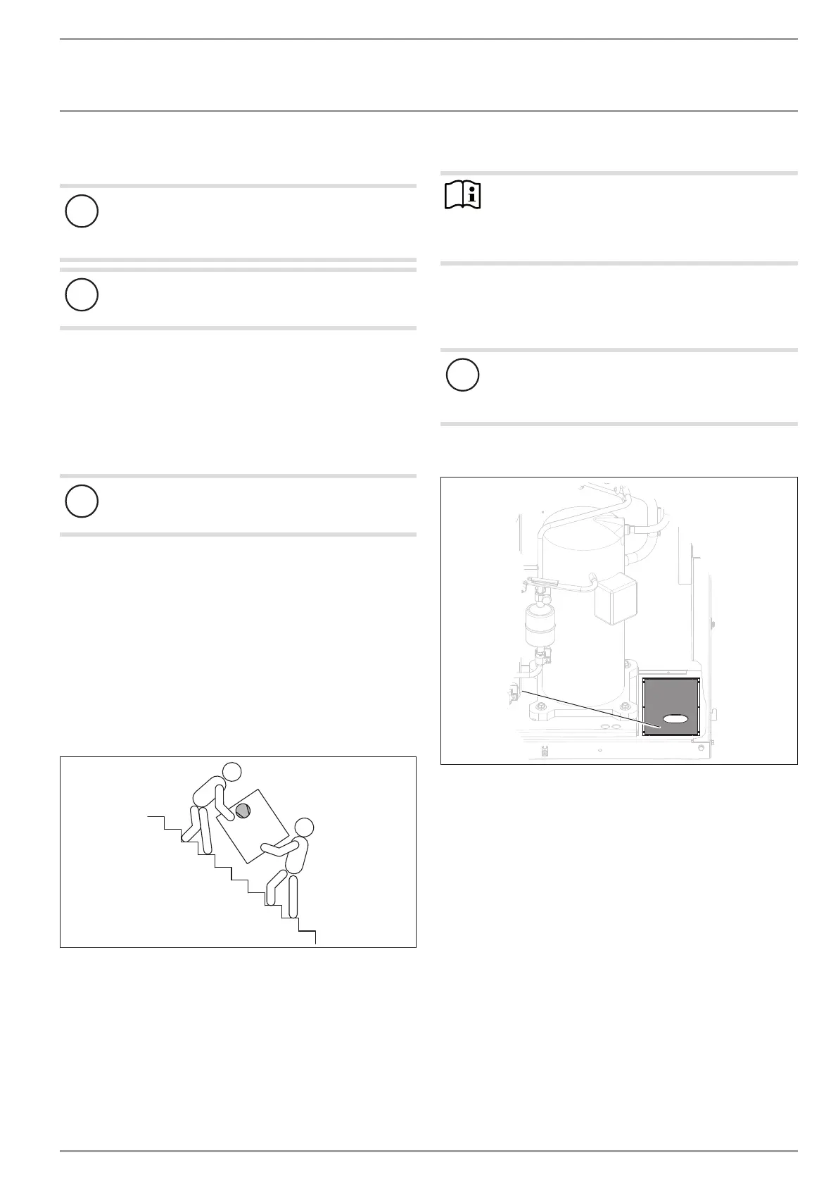
1
1 Knock-out "supply line entry"
Remove the knock-out "supply line entry" in the bottom of
the appliance.
Position the standard appliance on the prepared substrate.
Observe minimum clearances (see chapter "Preparations/
Minimum clearances").
ill]
====----
0
::::::::::C---=~==::;;::::::====:::::::::=---=--~
o
====----
0
0
--====

 Loading...


