Edition Manual Chapter Page
2014-09-09 Workshop Manual, GGP Park 6 Control wires 19
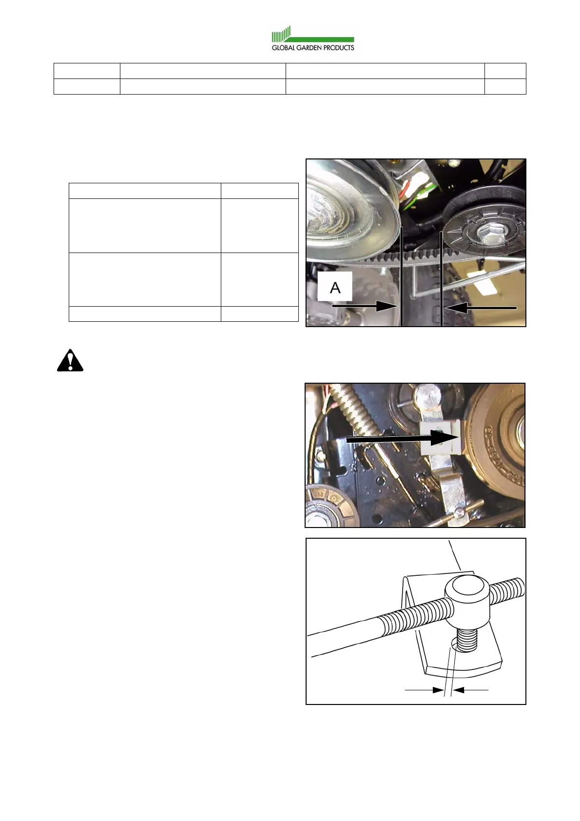
3. Adjust at the wire adjusting sleeves until the
space (A) between the tension pulley and
motor pulley coincide with the table below:
Warning!
It is important that the movement of
the tensioning arm is always
stopped by the brake pad, and not
by the engagement wire. If the wire
stops the movement, the braking ca-
pacity can be completely lost when
the parts become worn.
4. Press the brake shoe hard against the pul-
ley.
In this position, 1/4 of the hole shall be visi-
ble when the nipple is compared with its
hole.
Machine Measure (A)
2WD machines with the con-
trol panel to the right of the
operator, e.g. Comfort, Roy-
al, Senator etc.
30 mm
4WD machines with the con-
trol panel to the right of the
operator, e.g. Comfort, Roy-
al, Senator etc.
35 mm
Compact 20 mm
1/4 Dia.
 Loading...