Edition Manual Chapter Page
2014-09-09 Workshop Manual, GGP Park 6 Control wires 20
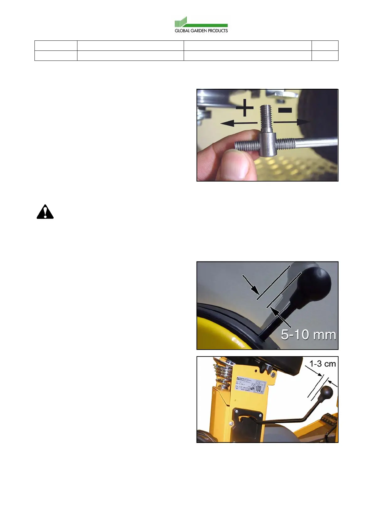
5. Adjust the nipple towards + to increase the
distance between the tension pulley and
the engine belt pulley, or towards - to
reduce.
6. When 1/4 of the hole is visible, fit the nipple
in the hole and assemble the nut as fol-
lows:
A. Screw on and tighten the nut moder-
ately.
B. Loosen the nut 1/2 turn.
The nipple shall be movable in the hole.
Warning!
If the nipple is tight in its hole, un-
normal stress will occour to the me-
chanical parts.
7. When the adjustment is complete, the fol-
lowing items shall be fulfilled:
• There is a clearance of 5-10 mm
respective 10-30 mm at the engage-
ment lever.
• Engage the power take-off and check
that the brake pad no longer brakes the
articulation belt pulley. If the brake pad
still brakes the belt pulley, move the nip-
ple some more.
• The brake pad will never completely
leave the groove in the belt pulley.
When the brake is correctly adjusted
the brake pad should be pulled out
approx. 1 mm from the innermost posi-
tion.
• Disengage the power take-off and
check that the power-take off brake
works.
If everything is correctly adjusted the
brake should be applied just enough for
the articulation belt pulley to be turned
round by hand only with extreme force.
• Check the stopping time as below.
 Loading...