ENGLISH
GB
SYMBOLS
The following symbols are displayed on the ma-
chine in order to remind you about the safety pre-
cautions and attention necessary when using the
machine.
The symbols mean:
Warning! Read the Instruction Book and
Safety Manual before using the machine.
Warning! Keep spectators away. Beware of
objects being flung out.
Warning! Before starting any repair work,
disconnect the plug from the wall socket.
Warning! Keep the extension cord away
from the cutting deck.
Warning! Do not put hands orfeet under the
cover of the machine when it is running.
Warning! The blades continue to rotate
even after the machine has been switched
off.
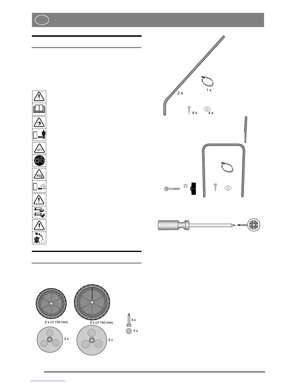
ASSEMBLING
PARTS TO ASSEMBLE
TOOLS FOR ASSEMBLEY
WHEELS/CUTTING HEIGHT (fig. 3)
1. Insert the wheel bolt A in the hub cap B.
2. Snap-on the centre cup C.
3. Fit the wheel in one of the fixing plate's four po-
sitions.
4. Tighten securely by hand using the finger-grip
holes in the hub cap.
NOTE! The samecutting height should be set on all
four wheels.
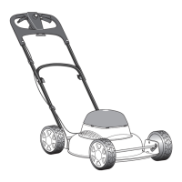
STEERING (fig. 1)
1. Insert a steering tube into the bracket on the left-
hand side as illustrated.
2. Slide in the steering's upper section.
3. Turn the entire steering in the opposite direction
as illustrated.
STOP
Wheel
Steering
2x
1x
1x
2x
2x
4x
4x
2x
Collapsible steering
 Loading...