WORKSHOP MANUAL
PARK PRO 900
Chapter
7 - Electrical System
EDITION
2022
Page
6
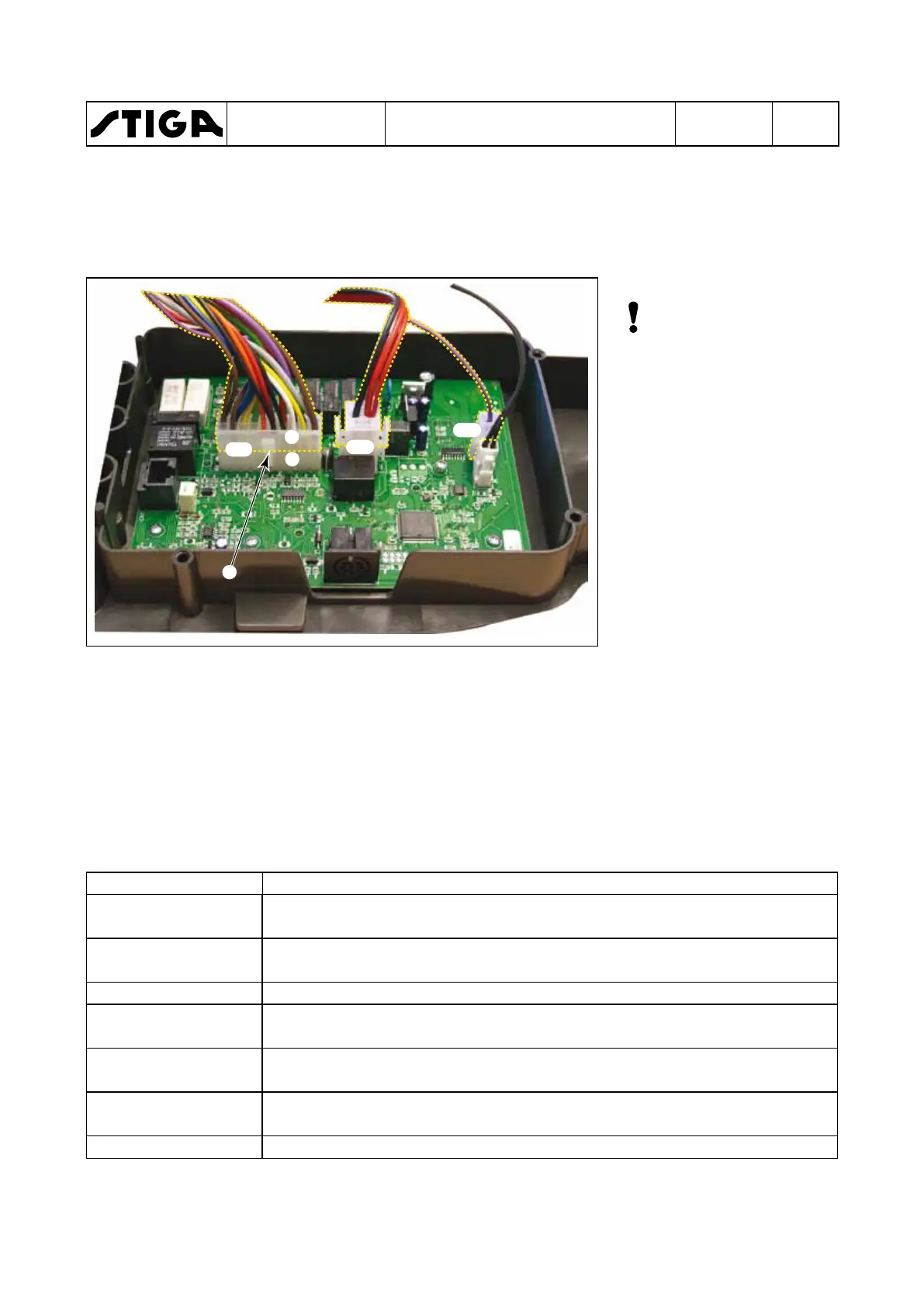
7.3 Electronic board
Note! The electronic
card is connected to
the system by means
of connectors CN1,
CN2 and CN3.
The connectors are divided
into two parts, the electron-
ic card side and the wiring
side.
E.g.: connector CN1 is di-
vided into (A) for the elec-
tronic side and (B) for the
wiring side.
The connector CN1 of the wiring is fitted with a lug (C) which locks it onto the female
connector on the electronic card.
7.3.1 Messages and information on the display
Messages will appear on the machine display; the following information corresponds to each
message string:
Message Meaning
CHECK
CONNECTION
When the sand spreader is enabled, a load with adequate
consumption is not detected.
NO MOVING
When the height of the rear accessory is adjusted, a load with
adequate consumption is not detected.
START ENGINE The PTO was started with the engine turned o - Start the engine.
PRESS BRAKE
You are trying to start the engine without engaging the brake - Press
the brake pedal.
SIT DOWN
You are trying to start the engine or enable the sand spreader without
sitting in the operator seat - Sit down in the operator's seat.
TILT SAVED
(for the Support Service only) - indicates the end of the inclinometer
calibration procedure.
TILT FAULT Indicates a malfunction of the tilt sensor.
B
A
CN1
CN2
CN3
C
 Loading...