29
8
DimplesUp
Dimples To
Inside
9
10
10
11
1
3
3
5
4
4
5
TOOLS NEEDED FOR ASSEMBLYTOOLS NEEDED FOR ASSEMBLY
TOOLS NEEDED FOR ASSEMBLYTOOLS NEEDED FOR ASSEMBLY
TOOLS NEEDED FOR ASSEMBLY
2
FRAME ASSEMBLYFRAME ASSEMBLY
FRAME ASSEMBLYFRAME ASSEMBLY
FRAME ASSEMBLY
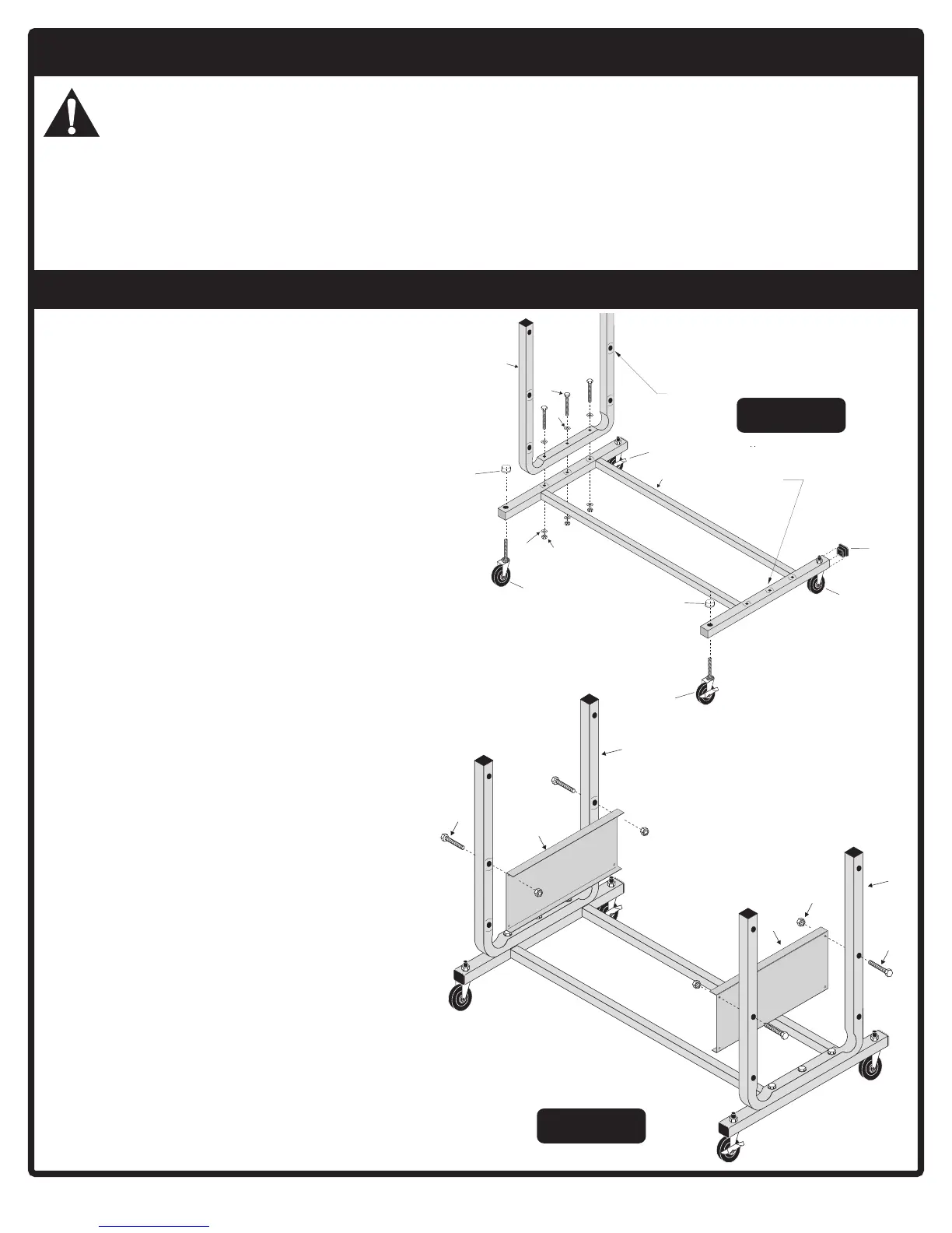
FIGURE 2FIGURE 2
FIGURE 2FIGURE 2
FIGURE 2
1. Open the hardware kit and sort all the hardware.
For your help in identifying hardware, see the
hardware identifier on the front of this manual.
2. Attach two non-locking casters #3 and two
locking casters #4 to frame base #1. NOTE:
Dimples in frame base should face up.
(See figure 1) Locking casters #4 must be
on opposite corners from each other.
Secure casters using Push nuts #5. Use a
hammer to tap push nuts onto caster stems
securely.
3. Put tube end caps #29 in the ends of the base
frame tubes #1. (See figure 1)
4. Attach "U" uprights #8 to base frame #1, with
dimples facing inward, using three bolts #9,
six washers #10 and three locknuts #11. (See
figure 1) Do not over tighten bolts crushing
tubes.
Note: One washer goes on top of "U"
uprights, and one goes under the base
frame. (See figure 1)
5. Attach name plate #14 to inside of "U" uprights
#8 using two bolts #12 and two locknuts #13.
Tighten these nuts securely BUT do not
over tighten them crushing tubes.
AT LEAST TWO ADULTS ARE NEEDED TO COMPLETE THE ASSEMBLY!
DO NOT LEAVE TABLE UNATTENDED UNTIL ASSEMBLY IS COMPLETE!
Tools Needed:Tools Needed:
Tools Needed:Tools Needed:
Tools Needed:n3/8 Open or Boxed End Wrench (2) n Rachet (optional)
n 7/16 Open or Boxed End Wrench (2) n 3/8 Socket (If using rachet)
n 1/2 Open or Boxed End Wrench (2) n 9/16 Open or Boxed End Wrench (2)
n Phillips Screwdriver n 9/16 Socket (If using rachet)
n Standard Screwdriver n Hammer
CAUTION
FIGURE 1FIGURE 1
FIGURE 1FIGURE 1
FIGURE 1
 Loading...