Illustration K
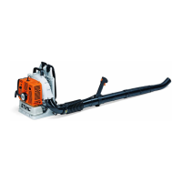
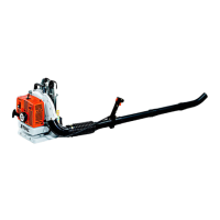
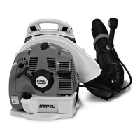
BR 500, BR 550, BR 600 23
Bedienungsgriff Control handle Poignée de commande
Bild-
Nr.
Teile-Nr. St.-
Zahl
Benennung Part Name Désignation
4282 790 1300 1 Bedienungsgriff
)
1 - 13
Control handle
)
1 - 13
Poignée de commande
)
1 - 13
1 4282 791 0800 1 Griffhälfte innen Handle molding, inner Monture de poignée intérieure
2 4282 182 2900 1 Stellhebel Locking lever Levier de réglage
3 9371 470 1060 1 Stift ISO2338-2m6x8 Cylindrical pin
ISO2338-2m6x8
Goupille cylindrique
ISO2338-2m6x8
4 4282 182 4300 1 Nocken Cam Came
5 4282 182 4520 1 Schenkelfeder Torsion spring Ressort coudé
6 9074 478 3075 6 Schraube IS-P4x19 Pan head self-tapping screw
IS-P4x19
Vis cylindrique IS-P4x19
7 4282 182 0800 1 Sperrhebel Trigger interlock Levier d'arrêt
8 4282 182 1000 1 Gashebel Throttle trigger Manette des gaz
9 4282 182 2800 1 Hebel Lever Levier
10 9131 378 0950 1 Gewindestift ISO4766--M5x10 Grub screw ISO4766--M5x10 Goupille filetée
ISO4766--M5x10
11 4282 182 4500 1 Schenkelfeder Torsion spring Ressort coudé
12 4282 180 1100 1 Gaszug Throttle cable Câble de commande des gaz
13 4282 791 0801 1 Griffhälfte außen Handlemolding,outer Monturedepoignée
extérieure
14 9074 478 4475 1 Schraube IS-P6x21,5 Pan head self-tapping screw
IS-P6x21.5
Vis cylindrique IS-P6x21,5
(1)BR500, (2)BR550, (3)BR600
 Loading...