STINGER ELECTRONICS (PTY) LTD BS120 INSTRUCTION MANUAL REF:03/2018
Printed: 4/26/2019 Page 8 of 20
OPERATING INSTRUCTIONS
Zone programming
Before starting, check the following fence conditions (with the HV wires
disconnected):
1. The DC resistance of the HV loop must be lower than 1200 Ohms.
2. The DC resistance between GND and the live wires must be higher than
100000 Ohms.
Programming
1. Switch the Energizer on to High Voltage Mode.
2. Press the “Program” button for 5 seconds. If the buzzer sounds, there is
a fence problem, which must be solved first. The problem may be a short
circuit or arcing.
3. Make a short circuit at zone split 1-2 (use the cable with crocodile clips),
the buzzer will sound, press the “Accept” button briefly.
4. Repeat step 3 until all zones have been programmed. After the last zone
press “Program” again to leave this routine. The remote control unit will
indicate the program status.
Remote Control Unit Connections
The standard connection cable can be extended to a length of a 100m.
This can be safely done if lightning in that area is not a problem.
Otherwise add a braided copper wire to the cable, which must be earthed at
both sides.
For longer distances the “Stinger” data radio should be used.
USE STINGER LIHGTNING DIVERTERS BETWEEN THE ENERGIZER GND CONNECTION AND THE
HV1 AND HV2 OUTPUTS.
USE A MAINS LIGHTNING PROTECTOR AT THE MAINS INPUT TO THE UNIT.
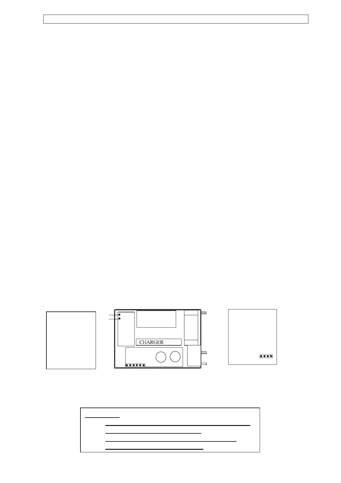
Connections
connector block:
1. Gate switch
2. Gate switch
3. Strobe light +
4. Strobe light –
5. Siren +
6. Siren -
Please note:
- The instrument is to be installed inside a building
or inside a water tight enclosure.
- No external apparatus to be connected to the
energizer power source (battery).
 Loading...