Do you have a question about the Stober POSIDRIVE MDS 5000 and is the answer not in the manual?
Provides information on the basic operation of the inverter and functions independent of standard applications.
Lists related manuals for POSITool software and other device documentation.
Defines technical abbreviations used throughout the document for clarity.
Lists trademarks of STÖBER and other companies used in the documentation.
Highlights the importance of safety guidelines, technical rules, and risk assessment for safe operation.
Specifies environmental requirements and applications that are prohibited for inverter use.
Defines the necessary qualifications for personnel performing tasks related to the device.
Details safety measures for installation, connection, and service, including power isolation.
Provides guidelines for proper disposal and outlines residual dangers associated with the device.
Explains how safety notes are presented and the meaning of different warning symbols.
Details the requirements and steps for placing an inverter into operation using its standard state machine.
Describes the device states as per DSP 402, which are similar to the standard device state machine.
Explains the conditions for state changes in the DSP 402 state machine.
Introduces parameters and their roles in adjusting applications and indicating values.
Details the hierarchical structure of parameters and their subject areas.
Lists and describes the different data types used for inverter parameters.
Explains the information required for addressing parameters via fieldbus, including data types.
Describes POSITool as the interface for programming, configuration, and parameterization.
Details the operator panel's functions for monitoring and changing parameter values.
Illustrates how to navigate through menu groups and parameters to change settings.
Guides users on selecting a STOBER motor via the configuration assistant in POSITool.
Explains how to use the electronic nameplate for servo motors to automatically read motor data.
Details how to manually enter motor data for non-standard motors or those without electronic nameplates.
Covers advanced motor data settings, including current controller, thermal model, and limit values.
Explains how to activate and parameterize the SLVC-HP control mode for AC motors.
Describes how to connect and parameterize motor temperature sensors for thermal protection.
Instructions on how to deactivate motor encoders when speed feedback is not required.
Details how to parameterize the integrated X4 interface for various encoder types.
Explains the connection and parameterization of binary input encoders using the X101 interface.
Guides users on parameterizing the X120 interface for SSI and TTL encoders.
Details the connection and parameterization of resolvers and EnDat encoders on interface X140.
Parameterizes brake control for the V/f-control mode.
Parameterizes brake control for sensorless vector control mode.
Parameterizes brake control for the SLVC-HP control mode.
Parameterizes brake control for vector control mode.
Parameterizes brake control for servo-control mode, using electronic nameplate or manual settings.
Describes axis management, including activation, deactivation, and allocation to motors.
Explains how axis selection is managed via binary signals and how to view axis management status.
Details the settings for establishing serial communication between PC and inverter.
Explains the methods and checks for establishing an online connection for data transfer.
Provides step-by-step instructions for safely replacing inverters with safety precautions.
Guides on changing the inverter's application by replacing the Paramodule.
Describes the process of copying a Paramodule to utilize an application in multiple inverters.
Details firmware files and the procedure for replacing or updating inverter firmware.
Explains how to execute inverter actions, categorized by whether they require motor energization.
Details specific actions like Phase Test, Autotuning, and winding tests for motor diagnostics.
Explains the meaning of LED indicators (ERROR, RUN) for determining the inverter's state.
Describes how the display provides detailed messages on inverter state, parameters, and events.
Details event indications, their reactions (message, warning, fault), and categories.
Lists specific event codes (e.g., 31:Short/ground, 32:Short/gr.int, 33:Overcurrent) and their solutions.
Covers troubleshooting for hardware faults (34:Hardw.fault) and watchdog errors (35:Watchdog).
Addresses faults related to high voltage (36:High voltage) and encoder issues (37:Encoder).
Details faults related to device temperature (38:TempDev.sens), thermal load (39:TempDev i2t), and brake resistor (42:TempBrakeRes).
Troubleshoots communication malfunctions (52:Communication) and parameter consistency errors (70:Param.consist).
Addresses firmware errors (71:Firmware) and configuration startup failures.
Covers faults related to brake tests (72:Brake test) and axis-specific brake tests (73-75).
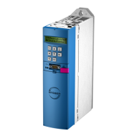
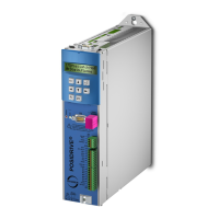
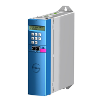
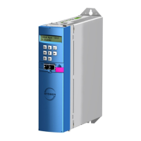
| Series | POSIDRIVE MDS 5000 |
|---|---|
| Cooling Method | Forced air cooling |
| Enclosure Rating | IP20 |
| Output Voltage | 0 to input voltage |
| Frequency Range | 0 to 400 Hz |
| Control Method | Vector control |
| Protection Features | Overload, short circuit, overvoltage, undervoltage |
| Communication Interface | CANopen, PROFIBUS, PROFINET |
| Operating Temperature | -10°C to 50°C |
| Storage Temperature | -25°C to 70°C |
| Humidity | 5% to 95% (non-condensing) |