Do you have a question about the Stoneridge Veeder-Root 2400 Series and is the answer not in the manual?
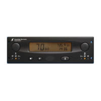
Describes the tachograph's integration as part of a wider system or instrument cluster.
Details the push-buttons used by drivers to initiate recorded duty periods.
Explains the function of the Light Emitting Diodes (LEDs) indicating work modes and faults.
Explains the push-button used for switching display modes and adjusting time.
Details the push-button for resetting trip values and adjusting clock settings.
Describes the push-button used to open the tachograph drawer for chart access.
Details the digital display area and the information it shows to the operator.
Procedure for setting the internal clock on units without a battery-backed real time clock.
Procedure for adjusting the offset of the internal clock on units with RTC.
Describes switching between odometer and trip distance display modes.
Explains how to access and view Diagnostic Trouble Codes (DTC) values.
Explains how to access and view the date and time associated with DTCs.
Step-by-step guide for inserting a tachograph chart for a crew member.
Step-by-step guide for inserting a tachograph chart for the driver.
Procedure for safely removing tachograph charts from the unit.
How to set the driver's current duty status using the push-button and LEDs.
How to set the crew member's current duty status using the push-button and LEDs.
Information on mandatory fields to be filled on tachograph charts at the start of a shift.
Instructions for manual chart entries in case of tachograph failure or specific activities.
How to record details when a driver transfers between vehicles during a shift.
Guidelines for maintaining the cleanliness of the tachograph unit.
Instructions on preventing damage to the tachograph from external factors and electrical issues.
| Brand | Stoneridge |
|---|---|
| Model | Veeder-Root 2400 Series |
| Category | Data Loggers |
| Language | English |