USER MANUAL
WWW.STRANDLIGHTING.COM
VISION.NET HARDWARE
8
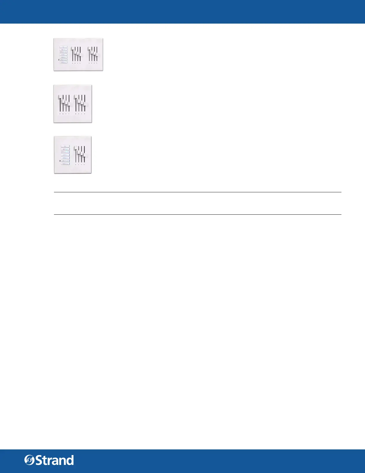
SLIDER BASE STATION
A Slider Base Station is a multiple gang panel that has a button station and a slider station
for channel control. The first slider is a Grand Master, the others are controlling channels.
You can configure the station to have channel sliders 1 through 16 with a separate Grand
Master. Shown is a 7 channel slider base for a 3 gang back box. For this type of station, the
bottom button is permanently configured to be a Manual button.
These sliders could be used for controlling the dierent channels of house lighting. (Or-
chestra section, wall sconces, aisle lights and down lights).
SLIDER EXTENSION
A Slider Extension is a potentiometer station that allows you to expand the number of
channels (up to 16 sliders) that can be controlled using sliders. Shown is an 8 slider station
for a 2-gang back box.
SUBMASTER BASE
A Submaster Base is a multiple gang panel that has a button station and a slider station for
submaster control. The first slider is a Grand Master, the others are controlling submasters.
You can configure the station to have from 1 to 16 sliders. Shown is a 3 submaster base for a
2-gang back box. For this type of station, the bottom button is permanently configured to
be a Manual button.
These submasters could be used to control all channels of house lighting together and to
store basic stage lighting looks for simple events (All house lights, stage wash and podium
looks).
NOTE: There is a paperclip hole on the hardware itself that allows recording at the station itself. Just set the
levels and insert a paperclip to press and hold. When the Learn function has occurred, the station will beep to
learn levels using Designer for Vision.Net.
1. UNDERSTANDING THE STATIONS
Vision.net products are controlled by the Strand Vision.net (SVN) protocol. All Vision.net control devices must
be connected to the Vision.net system and given a unique ID (or address) in order to interact properly. The ID
identifies the device on the network and allows the device to avoid network collisions when transmitting data.
On a multiple gang station, the first “gang” of the station has all the “intelligence” to connect to the Vision.net
RS485 network. The other “gangs” in the station are “dumb” and simply connect via a ribbon cable jumper thru
back to the first “gang” of the station.
PORTABLE STATIONS
Portable station is a wired Vision.net button/slider station that is available for remote operation. It is mounted in
an enclosure and tethered for connection into a Vision.net system. The tethered connection can be temporary or
permanent.
Portable stations can be standard Vision.net stations that reside in an enclosure and connect to the Vision.net
system via a permanently mounted 6-pin XLR connector. This gives the advantage of keeping the station pro-
gramming consistent to the portable station.
Portable stations can also be stations that contain no processing but connect to the Vision.Net system via a per-
manently mounted Smart Jack. This gives the advantage of keeping the programming in the Smart Jack itself.
INFRARED
Some button stations have infrared capabilities. An infrared remote is necessary to take advantage of this fea-
ture.
CONNECTIVITY
Stations are normally daisy chained together. In the event that it is not convenient to daisy chain all stations, a
Vision.net Four-Way Data Splitter can be used.
 Loading...