Do you have a question about the Stromberg-Carlson 125 and is the answer not in the manual?
Procedure for aligning the intermediate frequency circuits at 465 kilocycles.
Procedure for aligning radio frequency circuits at specified frequencies.
| Manufacturer | Stromberg-Carlson |
|---|---|
| Model | 125 |
| Category | Receiver |
| Circuit Principle | Superheterodyne |
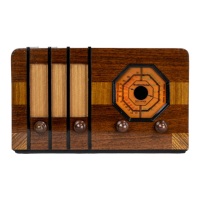
| Material | Wooden case |
| Type | Broadcast Receiver |
| Wave Bands | Broadcast |
| Power Type and Voltage | Alternating Current supply (AC) / 115 Volt |
| Power Supply | AC |
| Loudspeaker | Electrodynamic |
| Power Output | 1.5W |
| Shape | Table Model |