,-
Important:
The four M4 allen screws
(
3
ln fig. 8
)
should
not be
tightened
until
the two taper locating
pins (
2 in
fig. 8
)
have been
fltted.
Do not check the eccentrlclty of the capstan wlthout
pinch-wheel pressure
applled, as
bearing
play
may cause erroneous
readings.
C
7 Power Supply
for
Tape
Transport Mechanism
The
power
for the tape transport mechanism
and
the tape tenslon control clrcults ls supplled by a
separate
malns unlt, whlch is
mounted
in
the
centre
of the
cross-member
carrying the
spooling
motors.
See
fig.:
"Tape
Transport Mechanism".
To
gain
access
to the flxlng screws of this mains-unit,
the
spooling-plates and underlying dust
covers have to be
removed.
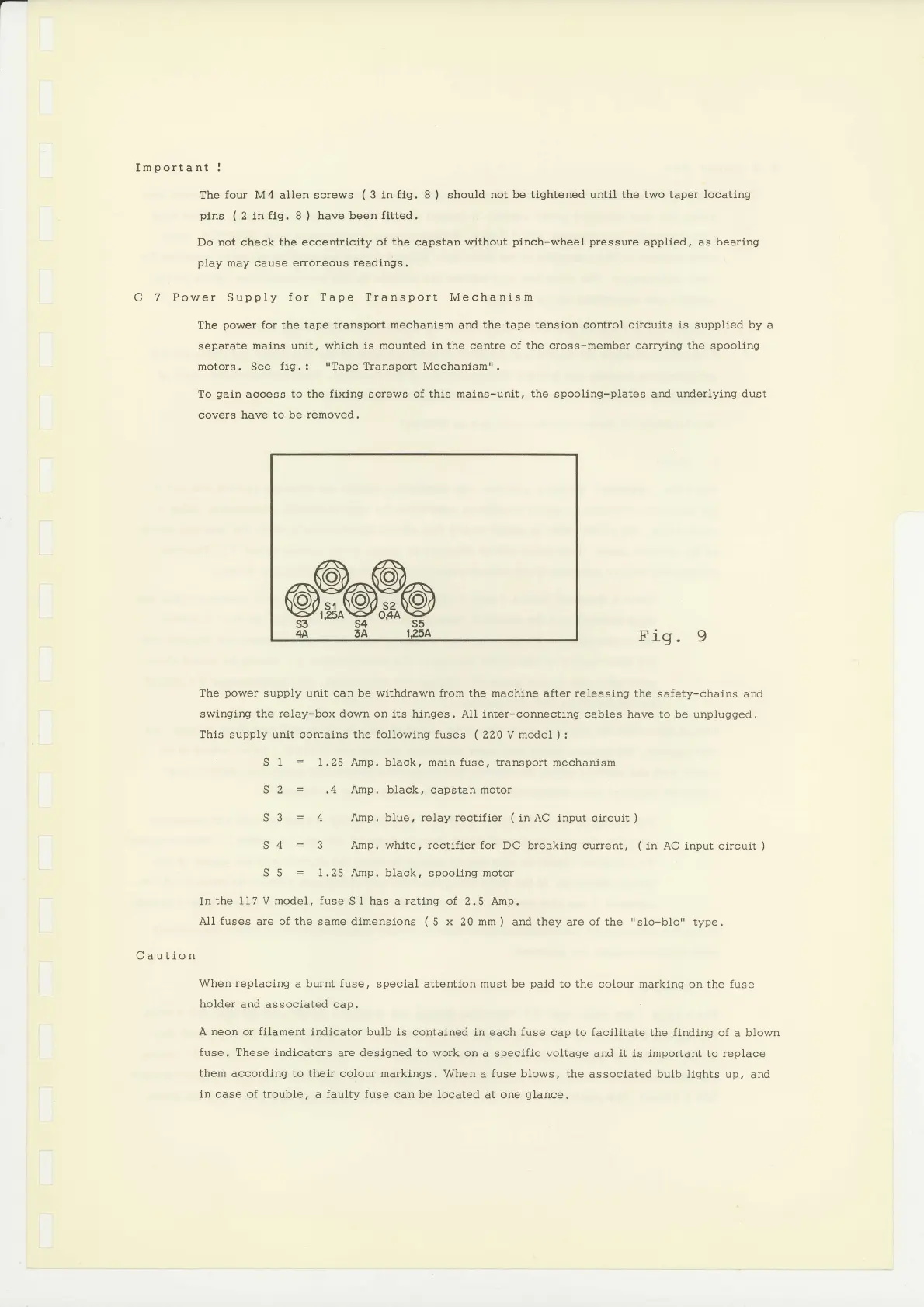
Fig.9
Caution
The
power
supply
unit can be wlthdrawn from
the machlne
after
releasing the
safety-chains
and
swlnging the
relay-box
down on its hinges. AII inter-connecting
cables have to be unplugged.
This supply unlt contains the following fuses
(
220 V
model
):
S
I
=
1.25
Amp. black, main fuse, transport mechanism
S
2
=
.4 Amp, black, capstan motor
S 3
=
4 Amp, blue, relayrectifier
(lnAC
lnputcircuit)
S
4
=
3
Amp.
whlte, rectifier
for DC breaklng
current,
(
in AC input circuit
)
S 5
=
1.25 Amp. black,
spooling
motor
In
the 1I7
V
model, fuse
S t has a rating of
2.5 Amp.
AII fuses
are
of
the same dimensions
(
5
x
20
mm
)
and
they
are of the
"slo-blo"
type.
When
replacing
a
burnt fuse,
speclal attention must be
paid
to the
colour
marking
on the fuse
holder
and associated cap.
A
neon
or filament irdicator bulb is contalned
ln each fuse cap to facilitate
the
finding
of a blown
fuse, These
indlcators are deslgned to work on
a specific
voltage
and
it is important
to replace
them according to their colour marklngs,
When a
fuse
blows, the
associated bulb lights up,
and
ln case
of
trouble, a
faulty
fuse can
be located at one
glance.
 Loading...


