playback
supply voltage can
be set by means
of RV, the record
supply voltage
by means
of RW;
the nominal value
ls 250 V. P I
should be
set
for minimum
ripple of
the record
HT-voltage.
Caution
:
The valves of the voltage
stablllzer unit must not
be removed
while the machlne
is
switched on.
It
isparticularlyimportantthattheplatecapsoftheregulatingvalves
VI and V4
(
E 130L)
are
replaced.
It can be seen from the circult
dtagram
(
7
.837 ,470
)
that otherwise
the entire
curent
would flow vla the
screen
grid
and
the
I00 Q resistor
in series with it. Thls
would overload
the
screen
grid
and
destroy
the valve.
D
5 Sync-playback
Amplifiers
A three
stage
voltage
amplifier ls
used
for
each channel wlth
a
frequency
selective
negative
feed-
back
clrcult between the
cathodes of the third
and the
first
stages.
The
tlme-constants
of the
clrcuits
are switched
to the
appropriate values
accordlng to the tape
speed ln use by means
of
a
relay
contact.
The output voltages
pass
through bias traps whlch
are tuned to the blas frequency
and are then
taken to the mixlng
clrcuit whlch is equipped
with
buffer
stages. The
subsequent
power
amplifier
is baslcly the
same
as the output
stage
of the replay
amplifiers. A
reslstance
network
ln the out-
put-clrcuit permlts
the use of low impedance
headphones for monitorlng
purposes.
The
sync-play-
,
.back
amplifier contains furthermore
a
monitor
amplifier which
ls also constructed
on the
same
lines
as the output stages of the
playback
channels.
D
6
Power
SuppIy Unit
for
Sync-playback Amplifiers
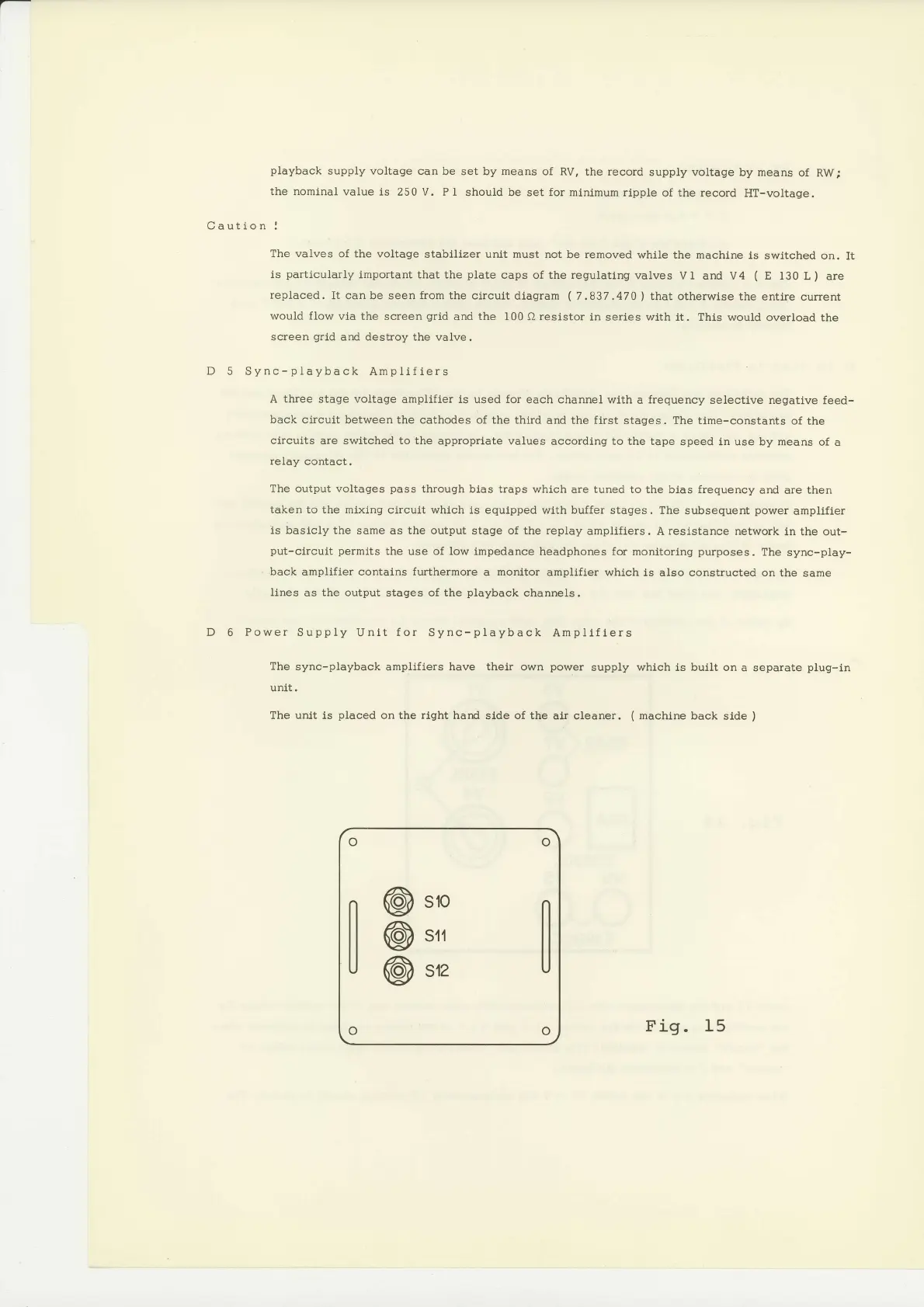
The
sync-playback
amplifiers have
their
own
power
supply whlch ls built on
a separate
plug-in
unit.
The unlt is
placed
on the rlght hard
side
of the
alr cleaner.
(
machlne back
slde
)
Fig. 15
U
@
@
@
s10
s{1
s12
 Loading...


