A
t
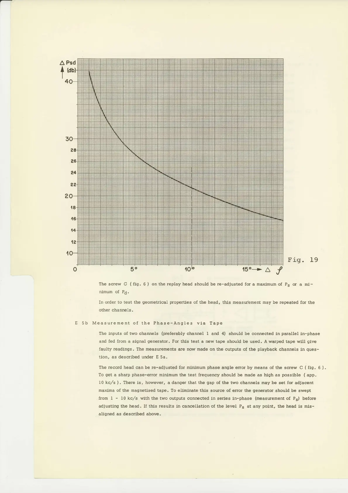
Fig. 19
Thescrew
C
(fig.6)
onthereplayheadshouldbere-adjustedforamaxlmumof
Ps or
a mi-
nlmum
of Pd.
In order to test the
geometrical properties
of the head,
thls measur'ement may be repeated for the
other
channels.
E
5b Measurement of the Phase-AngIes
via Tape
The inputs of two
channels
(preferably
channel I and 4) should be
connected in
parallel
in-phase
and
fed from
a slgnal
generator.
Por thls test
a
new tape
should be used. A warped tape wlll
glve
faulty readings. The measurements
are
now made
on the outputs
of the
playback
channels in
ques-
tion.
as descrlbed under
E
5a.
The
record
head can be re-adjusted for mlnlmum
phase
angle error by means of the
screw
C
(
fig.
6
).
To
get
a
sharp
phase-error
minlmum
the test
frequency
should
be made
as high as
posslble (
app.
I0 kc/s
).
There
ls,
however,
a danger that the
gap
of the two channels may
be set
for
adjacent
maxlma
of the magnetlsed tape. To eliminate this
source of error the
generator
should
be
swept
from
I
-
10 kc,/s wlth the two outputs connected
in series ln-phase
(measurement
of P") before
adjusting the head. If thls
results
in cancellatlon of the level P"
at any
point,
the head ls mls-
aligned as described above.