t--
Max.
permlsslble
phase
angle
between
any
2 channels:
Distortion:
a)
of the
ampllfiers ,
.I%
b) vla tape at
I kc,/s
2
Z%
at
200 mM
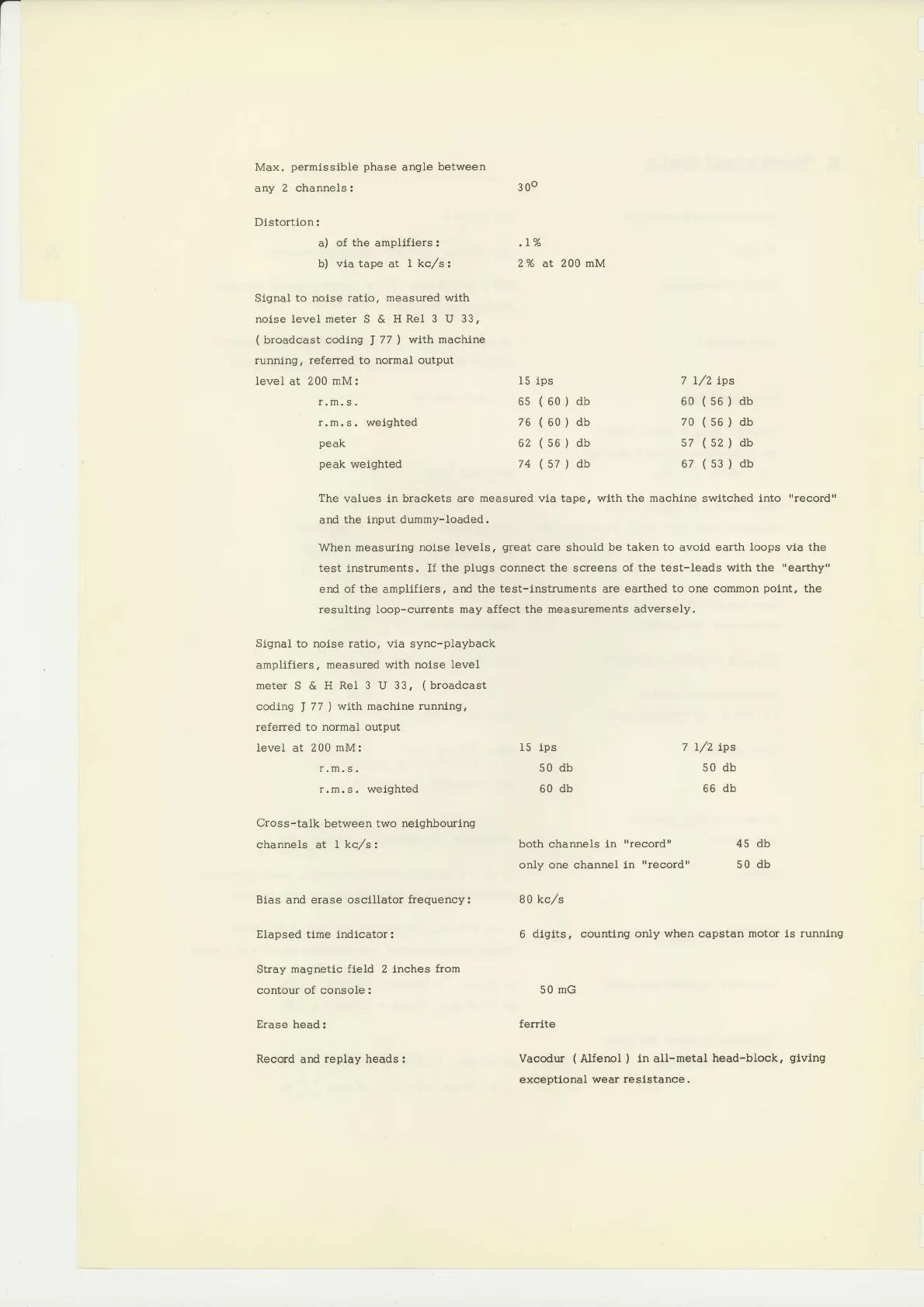
Slgnal
to noise ratlo, measured wlth
noise level
meter
S &
lI Rel 3 U 33,
(
broadcast coding
J
77
)
wlth machlne
running, referred to normal output
level at 200
mM:
15
ips
6s
(60)
db
76
(60)
db
62
(s6)
db
74
(s7)
db
Slgnal
to nolse ratio, via sync-playback
ampllfiers,
measured
wlth
nolse level
meter S & H
ReI 3
U
33,
(
broadcast
coding
J
77
)
wtth machine
runnlng,
referred to normal
output
level at 200
mM:
r. m.
s.
r.m.s. welghted
Cros
s-talk between two neighbouring
channels at I
kc,/s:
15 tps
50
db
60
db
7
L/2
tps
60
(s6)
db
70
(s6)
db
57
(s2)
db
67
(s3)
db
7 I/2 tps
50
db
66 db
both channels ln
'rrecord"
45 db
only one channel in
"record"
50
db
6 dlgtts,
countlng only
when
capstan
motor is runnlng
50
mG
ferrlte
Vacodur
(
Alfenol
)
ln all-metal head-block,
glvlng
exceptional wear
reslstance.
300
r.m,
s.
r.m.s.
weighted
peak
peak
weighted
The
values in
brackets
are
measured vla tape, wlth the machlne swltched
and
the input dummy-loaded.
when measurlng noise
levels,
great
care
should
be taken to
avold
earth loops via the
test instruments.
If the
plugs
connect
the
screens
of the test-Ieads wtth the
rrearthyrl
end of the
ampllflers,
ard the test-lnstruments are
earthed to one common
polnt,
the
resultlng loop-currents may affect the
measurements adversely.
Bias
and erase
oscillator frequency: 80 kc,/s
Elapsed tlme
indicator:
Stray
magnetic field
2
inches from
contour
of
console:
Erase head:
Recod
and
replay
heads:
 Loading...


