PR99
MKIII
5/8
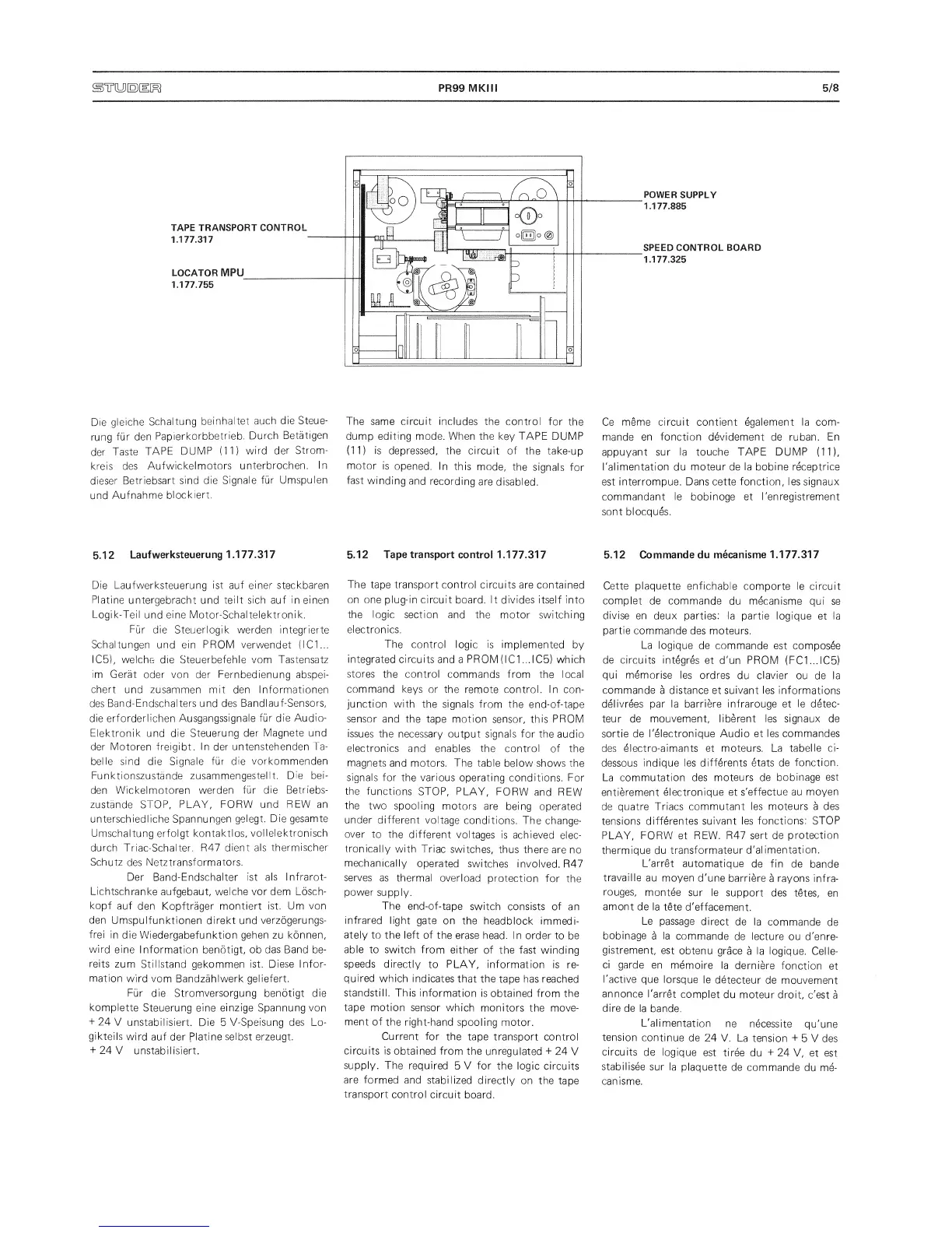
POWER
SUPPLY
1.177.885
SPEED CONTROL BOARD
1.177.325
Die
gleiche
Schaltung
beinhaltet
auch
die Steue-
rung
fur
den
Papierkorbbetrieb.
Durch
Betatigen
der
Taste
TAPE
DUMP
(11)
wird der
Strom-
kreis des
Aufwickelmotors
unterbrochen.
In
dieser
Betriebsart
sind
die
Signale
fur Umspulen
und
Aufnahme
blockiert.
5.12
Laufwerksteuerung
1.177.317
Die Laufwerksteuerung ist auf einer steckbaren
Platine
untergebracht und
teilt
sich auf ineinen
Logik-Teil
und
eine Motor-Schaltelektronik.
Fur die
Steuerlogik werden integrierte
Schaltungen
und
ein PROM
verwendet
(IC1...
IC5),
welche die Steuerbefehle vom Tastensatz
im
Ger¥ oder von der Fernbedienung
abspei-
chert
und zusammen mit den Informationen
des
Band-Endschalters und des
BandlauTSensors,
die erforderlichen Ausgangssignale
fur
die
Audio-
Elektronik
und die
Steuerung
der
Magnete und
der
Motoren
freigibt.
In
der
untenstehenden
Ta-
beile
sind die Signale
fur die
vorkommenden
Funktionszustande zusammengestellt.
Die bei-
den Wickelmotoren
werden fur
die Betriebs-
zListande STOP,
PLAY, FORW und
REW an
unterschiedliche Spannungen
gelegt.
Die gesamte
Umschaltung erfoigt
kontaktios,
vollelektronisch
durch
Triac-Schalter. R47
dient
als thermischer
Schutz
des
Netztransformators.
Der Band-Endschalter
ist als Infrarot-
Lichtschranke
aufgebaut, welche vor dem
Losch-
kopf
auf den
Kopftrager
montiert
ist.
Urn
von
den
Umspulfunktionen direkt und
verzdgerungs-
frei
in
die
Wiedergabefunktion
gehen
zu
konnen,
wird
eine
Information benotigt, ob
das Band
be-
reits
zum
Stillstand
gekommen
ist. Diese
Infor-
mation
wird
vom
Bandzahlwerk geliefert.
Fur die Stromversorgung benotigt die
komplette
Steuerung eine
einzige Spannung von
+
24
V unstabilisiert.
Die
5
V-Speisung des
Lo-
gikteils
wird auf der piatine
selbst
erzeugt.
+
24
V
unstabilisiert.
The
same
circuit
includes the control
for
the
dump
editing
mode.
When
the key
TAPE
DUMP
(11)
is
depressed, the circuit of
the take-up
motor
is
opened. In
this
mode,
the
signals
for
fast
winding
and
recording
are
disabled.
5.12
Tape transport
control 1.177.317
The
tape transport
control circuits
are contained
on one plug-in
circuit board. It
divides itself into
the logic section
and the motor switching
electronics.
The
control logic is
implemented
by
integrated circuits
and a
PROM (IC1
...IC5) which
stores
the control
commands from
the
local
command keys or the
remote control. In
con-
junction with the
signals from the
end-of-tape
sensor
and the tape motion
sensor, this
PROM
issues the necessary
output signals for the
audio
electronics
and
enables the control
of the
magnets
and
motors. The table
below shows the
signals
for the various operating
conditions. For
the
functions
STOP, PLAY,
FORW
and REW
the
two spooling
motors are
being
operated
under different
voltage
conditions.
The change-
over
to
the
different
voltages
is achieved
elec-
tronically
with
Triac
switches, thus
there
are no
mechanically
operated
switches
involved. R47
serves
as thermal
overload
protection
for
the
power
supply.
The
end-of-tape
switch consists of
an
infrared
light
gate
on the
headblock immedi-
ately to
the left of
the
erase head.
I
n
order to
be
able to
switch
from either
of the
fast winding
speeds
directly
to PLAY, information
is re-
quired
which indicates
that the
tape
has reached
standstill.
This
information
is
obtained from the
tape
motion sensor
which
monitors
the move-
ment of
the
right-hand spooling
motor.
Current
for the
tape transport
control
circuits is
obtained
from the
unregulated
-h
24
V
supply.
The required
5
V for the
logic
circuits
are formed
and
stabilized
directly
on the
tape
transport
control
circuit
board.
Ce
meme circuit contient egalement la
com-
mande
en function devidement
de ruban.
En
appuyant
sur la touche TAPE DUMP
(11),
I'alimentation du
moteur
de
la bobine receptrice
est interrompue. Dans cette
function, les signaux
commandant le bobinoge et
I'enregistrement
sont
blocques.
5.12
Commande du mecanisme
1.177.317
Cette plaquette enfichable
comporte le circuit
complet
de commande
du mecanisme
qui se
divise en
deux parties: la
partie logique
et la
partie
commande
des
moteurs.
La logique
de commande est
composee
de circuits
integres
et
d'un PROM (FC1...IC5)
qui memorise
les ordres
du
clavier
ou de la
commande
a
distance
et
suivant les
informations
delivrees par la
barriere infrarouge et
le
detec-
teur
de
mouvement, liberent
les signaux de
sortie de
I'electronique Audio et
les commandes
des
electro-aimants et moteurs. La
tabelie ci-
dessous
indique les
differents etats de
function.
La commutation des
moteurs de
bobinage
est
entierement
electronique et
s'effectue au
moyen
de quatre
Triacs commutant
les moteurs
a
des
tensions differentes
suivant les
functions: STOP
PLAY,
FORW
et
REW. R47 sert de
protection
thermique du
transformateur
d'alimentation.
L'arret
automatique
de fin de
bande
travaille
au moyen
d'une barriere
a
rayons infra-
rouges,
montee
sur le
support
des tetes,
en
amont
de la
tete
d'effacement.
Le
passage
direct
de
la
commande
de
bobinage
a
la
commande
de
lecture
ou
d'enre-
gistrement,
est
obtenu
grace
a
la logique.
Celle-
ci garde
en
memoire
la
derniere
function
et
I'active
que lorsque
le
detecteur
de
mouvement
annonce
l'arret
complet
du
moteur droit, c'est
a
dire de
la
bande.
L'alimentation
ne necessite
qu'une
tension
continue
de 24
V.
La
tension
+
5 V des
circuits
de logique
est tiree
du 24
V, et est
stabilisee
sur
la
plaquette
de
commande
du
me-
canisme.
 Loading...