DT[y©[i[R]
PR99
MKIII
5/10*
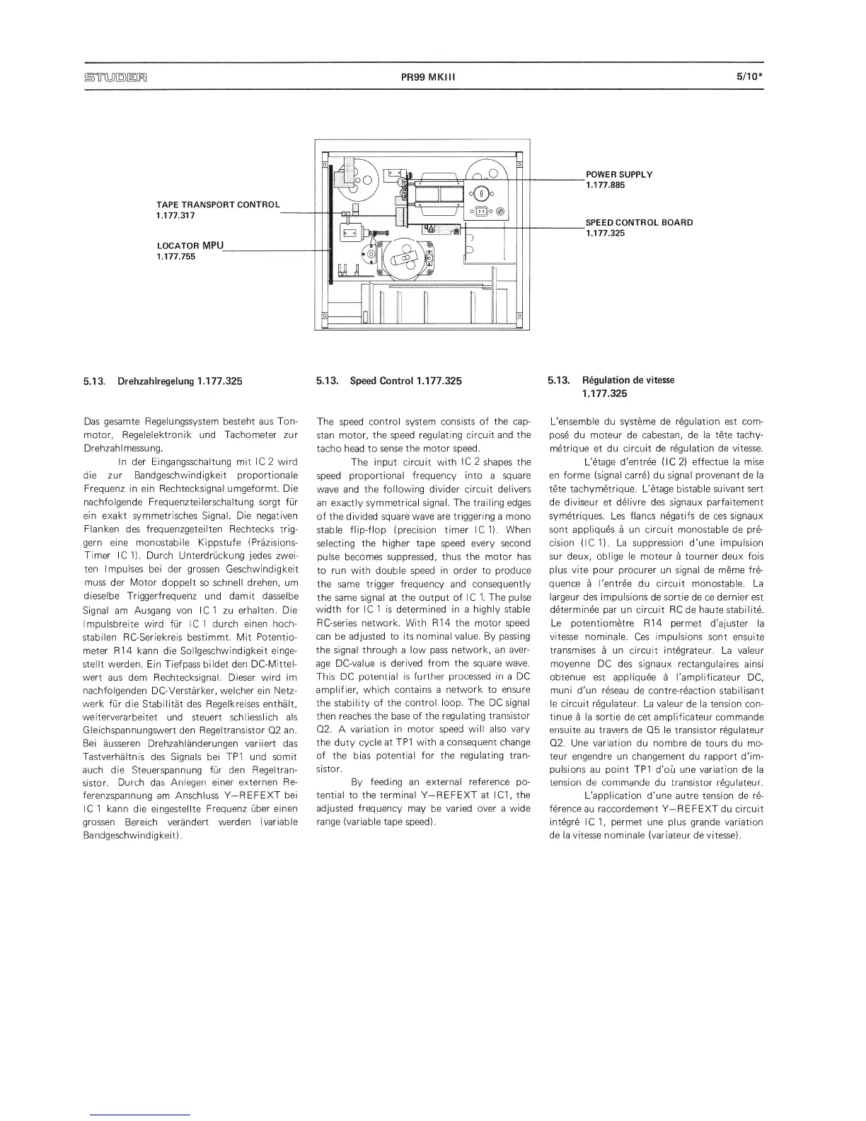
POWER
SUPPLY
1.177.885
SPEED CONTROL BOARD
1.177.325
5.13.
Drehzahlregelung 1.177.325
Das gesamte
Regelungssystem besteht aus Ton-
motor,
Regelelektronik und Tachometer
zur
Drehzahimessung.
In der Eingangsschaltung mit 1C 2
wird
die zur
Bandgeschwindigkeit proportionale
Frequenz
in
ein
Rechtecksignal umgeformt. Die
nachfolgende
Frequenzteilerschaltung sorgt fur
ein exakt symmetrisches Signal. Die negativen
Flanken
des
frequenzgeteilten Rechtecks trig-
gern eine monostabile Kippstufe (Prazisions-
Timer
1C 1). Dutch Unterdruckung jedes zwei-
ten Impulses bei der grossen
Geschwindigkeit
muss der Motor
doppelt so schnell
drehen,
um
dieselbe Triggerfrequenz
und
damit dasselbe
Signal am
Ausgang von
1C
1
zu
erhalten. Die
Impulsbreite wird fur
iC
1 dutch
einen
hoch-
stabilen RC-Seriekreis bestimmt. Mit
Potentio-
meter R14
kann die
Sollgeschwindigkeit einge-
stellt werden. Ein Tiefpass bildet den
DC-Mittel-
wert
aus dem Rechtecksignal.
Dieser
wird
im
nachfolgenden
DC-Verstarker,
welcher ein Netz-
werk fur die
Stabilitat des
Regelkreises
enthalt,
weiterverarbeitet
und steuert
schliesslich als
Gleichspannungswert
den
Regeltransistor
Q2 an.
Bei ausseren
Drehzahlanderungen variiert das
Tastverhaltnis
des Signals bei
TP1
und somit
auch die
Steuerspannung
fur den Regeltran-
sistor.
Dutch das
Aniegen
einer externen
Re-
ferenzspannung
am
Anschluss
Y—
REFEXT
bei
IC 1
kann die eingestellte
Frequenz uber
einen
grossen
Bereich
verandert werden
(variable
Bandgeschwindigkeit).
5.13.
Speed Control 1.177.325
The speed control system
consists of the cap-
stan
motor, the speed regulating
circuit and
the
tacho head
to
sense the motor speed.
The input
circuit with
IC
2
shapes the
speed
proportional frequency into a
square
wave and the
following divider circuit
delivers
an exactly symmetrical
signal. The trailing edges
of the divided square wave
are triggering
a
mono
stable
flip-flop (precision timer IC1). When
selecting the
higher tape speed every second
pulse becomes suppressed, thus
the motor has
to run with double
speed in
order
to produce
the same trigger frequency and
consequently
the same signal at the output
of IC 1. The pulse
width for IC
1
is
determined
in
a
highly stable
RC-series
network.
With R14
the motor speed
can
be adjusted to its nominal value. By
passing
the signal
through
a low
pass
network, an
aver-
age DC-value is
derived from the
square wave.
This
DC
potential
is further
processed in
a
DC
amplifier,
which contains a
network to
ensure
the stability
of
the control loop.
The
DC
signal
then reaches
the base of the
regulating
transistor
Q2.
A
variation
in motor speed will also
vary
the duty cycle
at TP1 with a
consequent change
of
the bias
potential for the
regulating tran-
sistor.
By feeding an external
reference
po-
tential to
the terminal Y—
REFEXT
at IC1, the
adjusted
frequency
may be varied
over
a
wide
range (variable tape speed).
5.13.
Regulation de
vitesse
1.177.325
L'ensemble
du
systeme
de regulation est com-
pose du moteur de
cabestan, de la tete tachy-
metrique
et
du circuit de regulation
de vitesse.
L'etage d'entree (IC2)
effectue
la
mise
en forme (signal carre) du signal provenant de la
tete
tachymetrique. L'etage bistable
suivant sert
de
diviseur
et
delivre des signaux parfaitement
symetriques.
Les flancs negatifs de ces
signaux
sont appliques
a
un circuit
monostable de pre-
cision
(IC1). La
suppression d'une
impulsion
sur
deux,
oblige
le
moteur
a
tourner
deux fois
plus
vite pour
procurer un signal de meme fre-
quence
a
I'entree du
circuit
monostable. La
largeur des impulsions
de
sortie de ce dernier est
determinee
par un circuit RC
de
haute
stabilite.
Le potentiometre
R14
permet
d'ajuster
la
vitesse nominale.
Ces impulsions sont ensuite
transmises
a
un
circuit integrateur.
La valeur
moyenne
DC des signaux rectangulaires
ainsi
obtenue est appliquee
a
I'amplificateur
DC,
muni d'un
reseau
de contre-reaction stabilisant
le circuit
regulateur.
La
valeur
de
la tension
con-
tinue
a
la sortie
de cet amplificateur commande
ensuite
au
travers
de Q5 le
transistor regulateur
Q2. Une variation
du nombre de tours du mo-
teur engendre un changement
du rapport d'im-
pulsions au point TP1
d'ou
une
variation de la
tension de
commande du transistor regulateur.
L'application d'une
autre tension de re-
ference
au
raccordement Y—
REFEXT du circuit
integre
IC
1,
permet une plus grande variation
de la
vitesse
nominale (variateur de vitesse).
 Loading...