Issue 1, October 1997 Model 770 User Guide
Page 28 Studio Technologies, Inc.
Model 770
In practice, calibrating the output level is
quite simple:
1. Confirm that the 1kHz direct output
is terminated with its normal load
impedance.
2. Ensure that the Model 770 is con-
nected to mains power.
3. Using an appropriate adapter cable,
connect an audio level meter directly
across the 1kHz direct output. Ensure
that your connection does not remove
the normal load! The level meter must
be a precision device thats intended
for audio usea general-purpose
voltmeter is not adequate!
4. Carefully observing the level meter,
adjust the trim pot to give the desired
output level.
Operation
While the Model 770 Audio Mixer/IFB
Controller is quite simple to operate, there
are nuances to its design that make a
detailed discussion worthwhile. Well start
with the individual sections that make up
the Model 770. Then well review how the
sections work together to become your
audio master control.
Mixer Section
Mic/Line Inputs
Three identical input channels are pro-
vided, each being compatible with a
microphone or line-level signal. A de-
tailed description of one mic/line channel
follows:
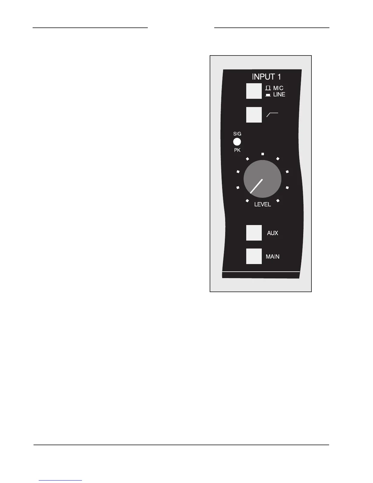
Input Sensitivity
The mic/line button is used to select the
sensitivity of the input circuitry. In the mic
(out) position, the expected nominal input
level is 55 to 35dBu. In the line (in)
position, a 40dB pad is inserted into the
circuit, making the expected nominal input
level 15 to +5dBu. The input circuitry is
compatible with a wide range of signal
levels and is protected from overload.
Low-Cut Filter
The button associated with the bent line
graphic symbol is used to select the low-
cut filter function. (If you are a stickler for
semantics, its actually a high-pass filter
Figure 10. Detail of front panel showing mic/
line input channel (typical of 3)