3 24
2
1
3
4
5
6
7
8
9
10
11
12
13
14
15
16
17
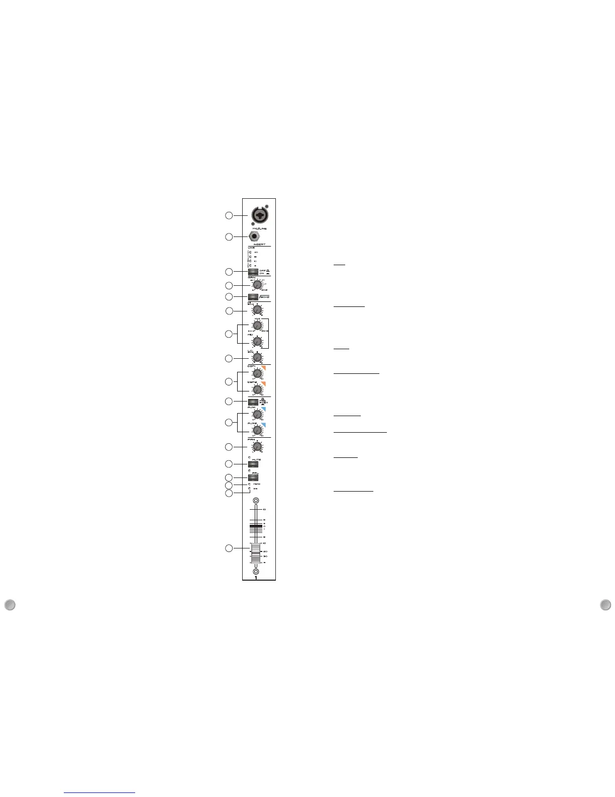
Controls & Features - Front Panel
Mic channels
1.Mic input channels
Combination 3 pin female XLR and ¼” TRS jack input socket.The Female XLR input
is suitable for use with low impedance dynamic microphones (for example the
Studiomaster KM range).Condenser microphones that require +48V can also be used
switch (68) located on the rear panel. Note: the +48V supply, if used will be is switche
in two banks: mic channels and stereo channels. Dynamic microphones can still be
used when the +48V is present but must be wired for balanced operation.Unbalanced
microphones could be damaged if connected to an input with +48V.The jack socket
input is suitable for keyboards, drum machines and other line level devices. Both inputs
can be used with balanced or unbalanced signals
2.INSERT socket
¼” jack TRS socket enabling the channel signal to be routed to an external processor
(like a vocal compressor) and returned back into the same channel. The signal to the
socket is sourced after (post) the EQ but before (pre) the fader.
3.Vocal Compressor
A studio quality compressor, derived from the Studiomaster VMS (Vocal Manage
ment System) is used to control the dynamics and give more 'body' to a vocal
performance. When switched on the compressor enters the signal chain immediately
after the Mic preamplifier & Hi Pass filter and before the EQ section.
Note: Not all Mic channels have this feature.
4.GAIN control
Adjusts the level of the incoming signal to match the operating level of the channel
for optimum signal to noise performance. The gain markings around the control are
Calibrated for the Mic input. Gain for the Line input will be 20dB lower.
5.Hi Pass filter
A steep low frequency filter that reduces microphone handling noise, stage rumble
And wind noise. Ideally it should always be active when a vocal microphone is used.
The frequency of the filter is 80Hz with a slope of 18dB/octave.
6.HI control
High frequency control providing 15dB of cut and boost at 12kHz with a peaking
response.
7.MID controls
The upper control sets the frequency the cut/boost control will influence within a
frequency range of 100Hz to 8kHz.The lower control provides 15dB of cut and boost.
8.LO control
Low frequency control providing 15dB of cut and boost at 60Hz with a peaking response.
9.DSP controls 1&2
Auxiliary sends to the on board effects processors and also to the DSP output sockets.
The signal is derived after (post) the channel fader and allows an independent mix of
each channel to the onboard effect processors. External effects processors can also
be connected using the signal available at the DSP output sockets.
TECHNICAL SPECIFICATION
Models 2012 2020
Mic channels 6 12
Stereo/mic channels 3 4
Total channel inputs 12 20
Compressors 3 4
Gain Min Max Range
10dB 56dB 48dBMic
-10db 36dB 48dBLine
Mic 8dB 56dB 48dBStereo
Line -11dB 20dB 31dBStereo
Equalization
Mic Channels +-15dB Hi 12kHz shelving, Mid 100-8kHz Q=1 peaking , Lo 80Hz shelving
Stereo Channels +-15dB Hi 12kHz shelving, Hi Mid 2.5kHz Q=0.7 shelving, Lo 45Hz shelving.
Auxiliary Sends+-15dB Hi 12kHz shelving, Mid 2.5kHz Q=0.7 shelving, Lo 60Hz shelving
Graphic +-9dB 63, 125, 250, 500, 1k, 2k, 4k, 8k, 16kHz, Q=1.7
Filters
Hi Pass Filter (all channels): 80Hz@18dB/oct
Notch Filter: 100Hz 7kHz, -9dB, Q=2.4
Vocal Compressor
Threshold: -20dB
Ratio: 4:1
Attach time: 1mS
Release time: 100mS
Crossover: 100Hz, 18dB@oct
Hi pass assigned to MIX output, Lo pass assigned to MIX2 output.
Frequency Response
Inputs to MIX output +0,-1dB 12-45kHz
Amplifiers +0,-1dB 20-38kHz
Distortion
Mic input to MIX outputs: 0.025%
Amplifier input to speaker outputs 0.03%
Mic input to speaker outputs: 0.05%
Noise 20-20kHz
Mic EIN, A-weighted -130dBu
Signal to Noise ratio, A-weighted,
Mic to Speaker output: 93dB
Mix outputs Residule, Un-weighted -104dBu
Mix faders at 0dB, Un-weighted -82dBu
 Loading...