Do you have a question about the Stulz CyberAir 3 PRO DX ASR Series and is the answer not in the manual?
| Brand | Stulz |
|---|---|
| Model | CyberAir 3 PRO DX ASR Series |
| Category | Air Conditioner |
| Language | English |
Symbols and their meanings related to safety.
General safety guidelines and precautions for operation and maintenance.
Guidelines for safe handling and regulations concerning refrigerants.
Requirements for refrigerating plants in the EU, installation, operation, and inspection.
Packaging, information on packing, and checking units upon delivery.
Methods for moving units safely using lifting devices and forklifts.
Measures to protect units from damage and corrosion during intermediate storage.
Explanation of the unit variant identification system found on the rating plate.
Specifies the intended use of the A/C unit for indoor temperature and humidity control.
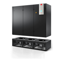
Describes the main components like fan unit and heat exchanger unit.
Explains how the unit operates, including cooling and dehumidification processes.
Admissible operating conditions for temperature, humidity, and storage.
Technical specifications for ASR...A units with one refrigerant circuit.
Technical specifications for ASR...A units with two refrigerant circuits.
Technical specifications for ALR...GE units with one refrigerant circuit.
Technical specifications for ALR...GE units with two refrigerant circuits.
Technical specifications for ASR...AS units with one refrigerant circuit.
Technical specifications for ASR...AS units with two refrigerant circuits.
Technical specifications for ALR...GES units with one refrigerant circuit.
Technical specifications for ALR...GES units with two refrigerant circuits.
Diagrams showing the physical dimensions and sizes of the units.
Guidelines for selecting an installation site and positioning the unit correctly.
Instructions for connecting refrigerant and water piping systems.
Details for connecting refrigerant lines to A/AS units and external condensers.
Instructions for connecting water piping for GE/GES units to external systems.
Location and installation of the condensate drain and syphon.
Procedures and diagrams for connecting electric cables to the fan unit and main unit.
Safety precautions for maintenance work and potential hazards.
Table outlining recommended maintenance schedules for various components.
Procedures for checking refrigerant quantity, purity, and HP switch.
Maintenance for heat exchanger, fan, and air filter.
Checks for water circuit tightness and condenser condition.
General checks for electrics and mechanics of the unit.
Required qualifications for different types of repair work.
Description of the steam humidifier OEM2 and its operation.
Technical specifications for the steam humidifier, including power and operating conditions.
Electrical wiring diagram for the steam humidifier control unit.
Settings for capacity limitation, control signal, and general unit parameters.
Function of the display and operating elements on the control unit.
Step-by-step guide for putting the steam humidifier into operation.
Troubleshooting guide for steam humidifier malfunctions and fault indications.
Describes the different types of reheat systems and their connections.
Notes on operation as controlled by the unit's controller.
Annual cleaning and inspection requirements for reheat systems.
Installation instructions for connecting a duct to the unit top.
Details on the optional bag filter for pre-filtration of air.
Information on the optional sound insulation plenum for noise reduction.
Mounting adapter plates for dampers or flexible connections on the unit top.
Guidelines for clearances and securing the unit on a raised floor stand.
Steps for correctly positioning and securing the fan unit on the floor stand.
Functionality of the phase monitoring relay and its adjustment settings.
Option for connecting a second power supply with priority switching.
Description and configuration of the compressor softstart controller.
Description of the manual override board for component control during controller failure.


