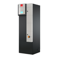
Do you have a question about the Stulz Mini-Space DX CCD221A and is the answer not in the manual?
Explains safety symbols and their meanings.
General safety guidelines for operation, maintenance, and handling.
Guidelines for safe handling and disposal of refrigerants.
Outlines European Community requirements for refrigerating plants.
Details residual risks during transport and installation phases.
Details residual risks during the unit's start-up process.
Details residual risks during the unit's operation.
Details residual risks during maintenance activities.
Details residual risks during dismantling and disposal.
Information regarding the delivery and packaging of A/C units.
Guidelines for safely transporting the A/C units.
Recommendations for storing the A/C units to prevent damage.
Explanation of the unit's type code and rating plate information.
Specifies the intended application and environment for the A/C unit.
Describes the operational principles and functions of the A/C unit.
Defines the operating and environmental limits for the unit.
Specifies design conditions for technical data, including electrical and fluid parameters.
Details the settings for pressure switches (LP, HP, Safety valve).
Provides detailed technical specifications for various unit types.
Illustrates the physical dimensions of the A/C unit's cabinet sizes.
Guidelines for selecting and preparing the installation site.
Instructions on how to access the unit's internal components.
Instructions for connecting the unit's piping systems.
Details location and dimensions of refrigerant connections for downflow units.
Step-by-step guide for filling the refrigerant circuit.
Instructions for connecting the external water circuit and handling water quality.
Explains syphon installation and drain connection requirements.
Safety and connection instructions for electrical supply.
Steps for initial unit setup and checks before operation.
Details controller adjustments and checks during initial operation.
Safety precautions for performing maintenance work.
Schedule for routine maintenance tasks for various components.
Procedures for checking refrigerant quantity, purity, and handling leaks.
Maintenance considerations for heat exchanger, fan, and air filter.
Checks for water circuit tightness and condenser condition.
General checks for electrical connections and mechanical integrity.
Specifies required qualifications for repair work.
Lists common alarm messages and their potential causes.
Procedures and safety guidelines for dismantling and disposing of the unit.
Lists EC directives and harmonised EN standards the unit complies with.
Explains the function and components of the steam humidifier.
Provides technical specifications for the steam humidifier.
Illustrates the electrical connections for the steam humidifier control unit.
Details how to configure the control unit for the steam humidifier.
Instructions for water supply and drain connections for the humidifier.
Explains the controls and indicators on the steam humidifier's control unit.
Step-by-step guide for putting the steam humidifier into operation.
Describes how the control unit indicates malfunctions via LEDs.
Comprehensive list of malfunctions, causes, and remedies for the humidifier.
Instructions for replacing a fuse on the humidifier control unit.
Procedure to reset error indicators after fault resolution.
Refers to a service manual for detailed maintenance procedures.
Introduces optional reheat functions (Electrical, HW, HG).
Details installation requirements and potential malfunction causes for reheat.
Describes the EU5 filter as an upgrade for air filtration.
Explains the function and connection of the condensate pump.
Details the air discharge design for downflow units.
Describes the air discharge plenum for upflow units.
Details the unit base design for downflow and upflow air discharge.
Explains the base for duct connection and air damper installation.
Details the air damper for upflow units and its installation.
Describes the adaptor plate for mounting an air damper below downflow units.
Details the air damper for downflow units and its installation.
Installation of filter top with flexible duct for downflow units.
Explains the Ecocool function for free cooling and its controls.
Details the louver actuators used in the Ecocool system.
Provides dimensions for Size 1 downflow units with Ecocool louvers.
Provides dimensions for Size 2 downflow units with Ecocool louvers.
Describes the raised floor stand for unit installation and its dimensions.
Guidelines for installing raised floor stands with minimum distances.
Instructions for correctly positioning the unit on the floor stand.
Details the phase monitoring relay and its settings for safety.
Configuration for automatic unit restart after power issues.
Describes the option of a second power supply for redundancy.
Specifies cable cross-sections and requirements for power supply lines.
Explains the hot gas bypass option for enhancing the refrigerant circuit.
Explains the suction throttle option for enhancing the refrigerant circuit.
Details the adjustable high and low-pressure switches for system protection.
| Brand | Stulz |
|---|---|
| Model | Mini-Space DX CCD221A |
| Category | Air Conditioner |
| Language | English |


