Planning Information
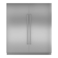
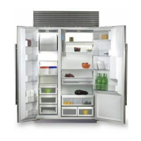
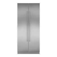
Integrated Model 700BF(I)
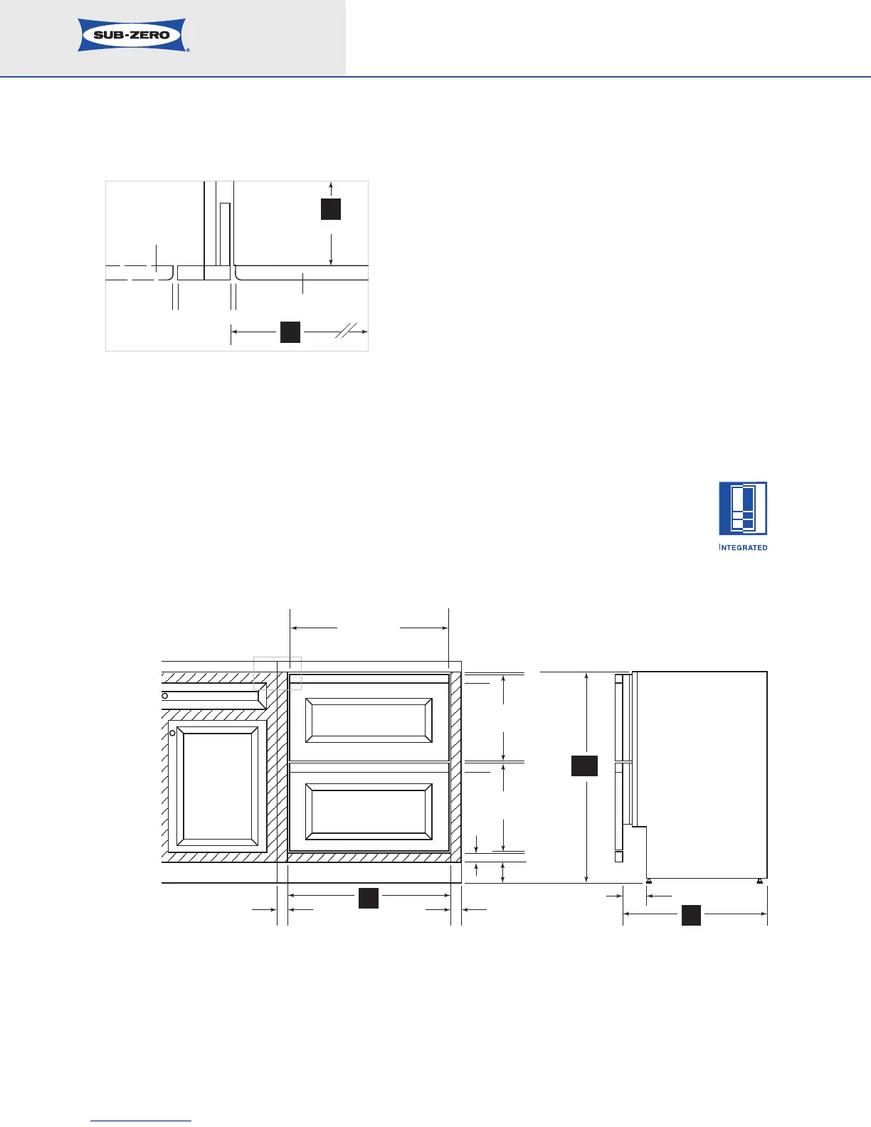
Installation of an Integrated drawer unit
within fr
amed ca
binetry.
*Dimensions may vary.
Dimensions in parentheses are in
millimeter
s unless otherwise specified
.
8
A) ALL REVEALS ARE 1/8" (3)
B) DRAWER RAILS ARE ATTACHED TO DRAWER FRONTS
C) BOTTOM RAIL MUST BE REMOVABLE
*DIMENSIONS MAY VARY
C
A
A
A
B
B
PANEL WIDTH
1
1
/2"
(38)
FRONT VIEW SIDE VIEW
26
3
/4" (679)
13
9
/16"
(345)
15
1
/16"
(383)
1
1
/2"
(38)
1
1
/2"
(38)
4"*
(102)
4" (102)
34
1
/2"
(876)
*
24"
(610)
27"
(686)
SHADED AREA
INDICATES STATIONARY
STYLES AND RAILS
TOP VIEW
A A
PANEL
CABINET DOOR
TO WALL
SUB-ZERO
UNIT
27"
(686)
24"
(610)
The illustration shows an Integrated drawer unit
installed within a framed cabinetry beaded inset
application.
IMPORTANT NOTE: Dimensions are based on a
1
/8" (3)
reveal. A reveal of up to
1
/4" (6) is possible, but panel
d
imensions need to be adjusted accordingly.
FRAMED CABINETRY – BEADED INSET APPLICATION