ABS-35
ABS (DIAGNOSTICS)
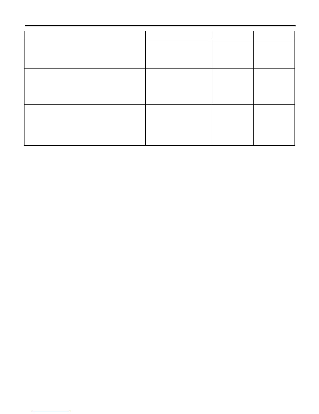
DIAGNOSTICS CHART WITH DIAGNOSIS CONNECTOR
10 CHECK WIRING HARNESS.
Measure resistance between connector (F74)
and chassis ground.
Connector & terminal
(F74) No. 20 — Chassis ground:
Is the resistance less than 0.5
Ω
?
Go to step
11.
Repair harness.
11 CHECK WIRING HARNESS.
1)Connect connector to ABSCM&H/U.
2)Measure resistance between connector
(F74) and chassis ground.
Connector & terminal
(F74) No. 20 — Chassis ground:
Is the resistance more than 1
M
Ω
?
Go to step
12.
Repair harness.
12 CHECK POOR CONTACT IN ABSCM&H/U
CONNECTOR.
Is there poor contact in
ABSCM&H/U connector?
Repair connector. Replace
ABSCM&H/U.
<Ref. to ABS-7,
ABS Control Mod-
ule and Hydraulic
Control Unit
(ABSCM&H/U).>
Step Check Yes No
 Loading...