ABS-52
ABS (DIAGNOSTICS)
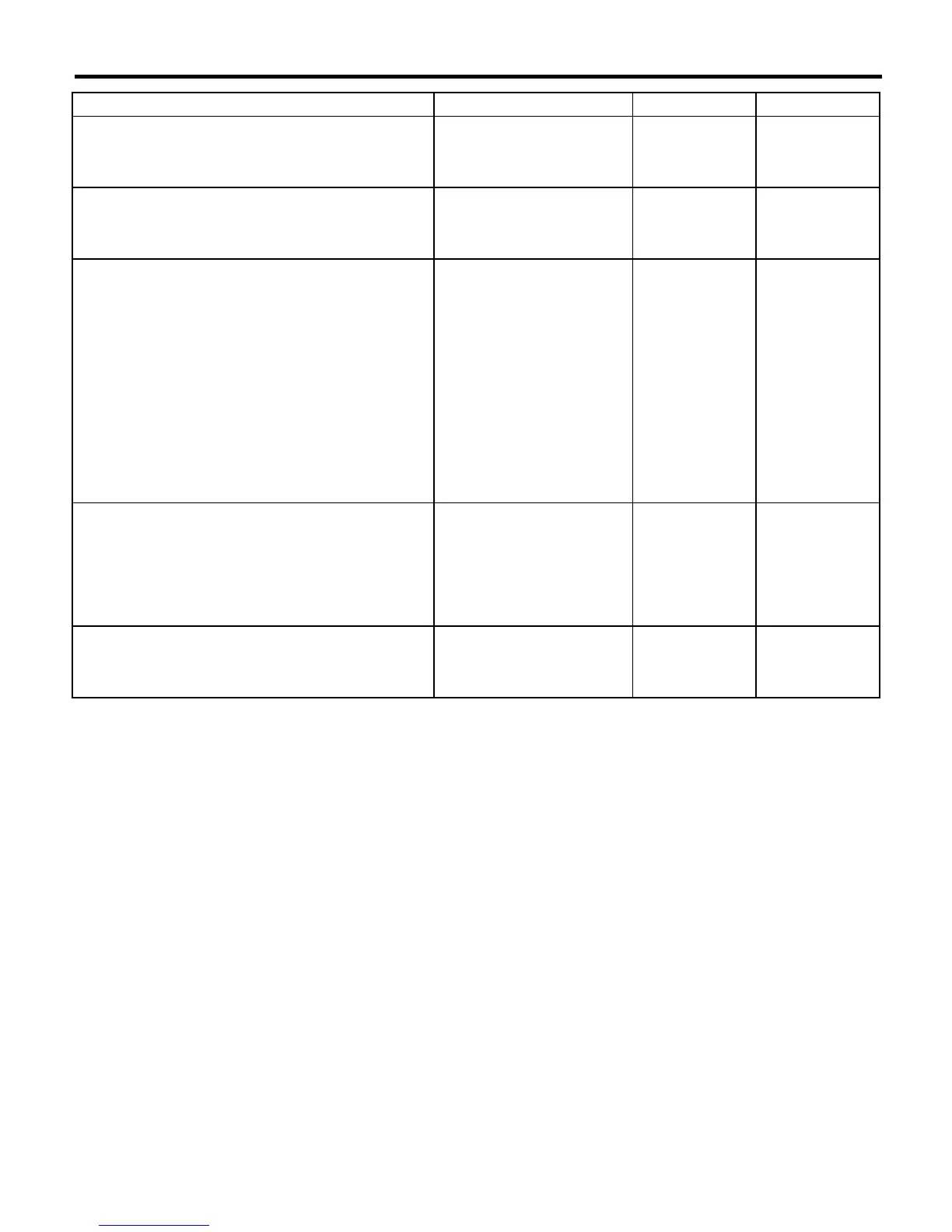
DIAGNOSTICS CHART WITH DIAGNOSIS CONNECTOR
14 CHECK SOURCES OF SIGNAL NOISE.
Is the car telephone or the
wireless transmitter properly
installed?
Go to step
15.
Properly install the
car telephone or
the wireless trans-
mitter.
15 CHECK SOURCES OF SIGNAL NOISE.
Are noise sources (such as an
antenna) installed near the
sensor harness?
Install the noise
sources apart from
the sensor har-
ness.
Go to step
16.
16 CHECK SHIELD CIRCUIT.
1)Connect all connectors.
2)Measure resistance between shield connec-
tor and chassis ground.
Connector & terminal
Trouble code 26 / (B200) No. 11 — Chas-
sis ground:
Trouble code 28 / RHD: (B200) No. 1 —
Chassis ground:
Trouble code 28 / LHD: (B200) No. 3 —
Chassis ground:
NOTE:
For the
Trouble code 22
and
24
:
Go to step
17.
Is the resistance less than 0.5
Ω
?
Go to step
17.
Repair shield har-
ness.
17 CHECK ABSCM&H/U.
1)Connect all connectors.
2)Erase the memory.
3)Perform inspection mode.
4)Read out the trouble code.
Is the same trouble code as in
the current diagnosis still being
output?
Replace
ABSCM&H/U.
<Ref. to ABS-7,
ABS Control Mod-
ule and Hydraulic
Control Unit
(ABSCM&H/U).>
Go to step
18.
18 CHECK ANY OTHER TROUBLE CODES AP-
PEARANCE.
Are other trouble codes being
output?
Proceed with the
diagnosis corre-
sponding to the
trouble code.
A temporary noise
interference.
Step Check Yes No
 Loading...