VDC-259
VDC (DIAGNOSTICS)
DIAGNOSTICS CHART WITH SELECT MONITOR
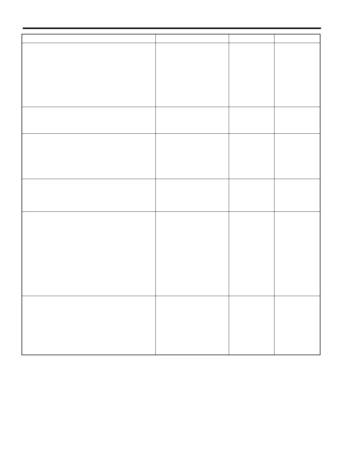
Step Value Yes No
1 CHECK OUTPUT OF YAW RATE AND LAT-
ERAL G SENSOR USING SELECT MONI-
TOR.
1) Stop the vehicle on a flat road.
2) Select “Current data display & Save” on the
select monitor.
3) Read yaw rate and lateral G sensor output
on the select monitor display.
Is the measured value within the specified
range?
2.3 — 2.7 V Go to step 2. Go to step 5.
2 CHECK POOR CONTACT IN CONNECTORS.
Turn ignition switch to OFF.
Is there poor contact in connector between
VDCCM and yaw rate and lateral G sensor?
There is poor contact. Repair connector. Go to step 3.
3 CHECK VDCCM.
1) Connect all connectors.
2) Erase the memory.
3) Perform inspection mode.
4) Read out the diagnostic trouble code.
Is the same diagnostic trouble code as in
the current diagnosis still being output?
Same DTC indicated. Replace VDCCM.
<Ref. to VDC-8,
VDC Control Mod-
ule (VDCCM).>
Go to step 4.
4 CHECK ANY OTHER DIAGNOSTIC TROU-
BLE CODES APPEARANCE.
Are other diagnostic trouble codes being out-
put?
Other DTC indicated. Proceed with the
diagnosis corre-
sponding to the
diagnostic trouble
code.
A temporary poor
contact.
5 CHECK INPUT VOLTAGE OF YAW RATE
AND LATERAL G SENSOR.
1) Turn ignition switch to OFF.
2) Remove console box.
3) Disconnect connector from yaw rate and
lateral G sensor.
4) Turn ignition switch to ON.
5) Measure voltage between yaw rate and lat-
eral G sensor connector terminals.
Connector & terminal
(R100) No. 3 (+) — No. 6 (
−
−−
−
):
Is the measured value within the specified
range?
10 — 15 V Go to step 6. Repair harness/
connector
between yaw rate
and lateral G sen-
sor and VDCCM.
6 CHECK YAW RATE AND LATERAL G SEN-
SOR.
1) Turn ignition switch to OFF.
2) Measure resistance between yaw rate and
lateral G sensor terminals.
Terminals
No. 3 — No. 5:
Is the measured value within the specified
range?
4.3 — 4.9 kΩ Go to step 7. Replace yaw rate
and lateral G sen-
sor. <Ref. to VDC-
22, Yaw Rate and
Lateral G Sensor.>








 To Next Page