3 Suburban DynaPack H Series Owner's Manual 10/2017 Rev.4
CONDENSATE DRAIN - FURNACE
The high efficiency furnace in this unit will produce condensate when operating.
In addition, a trap is needed in order to overcome the negative pressure produced
by the combustion inducer blower.
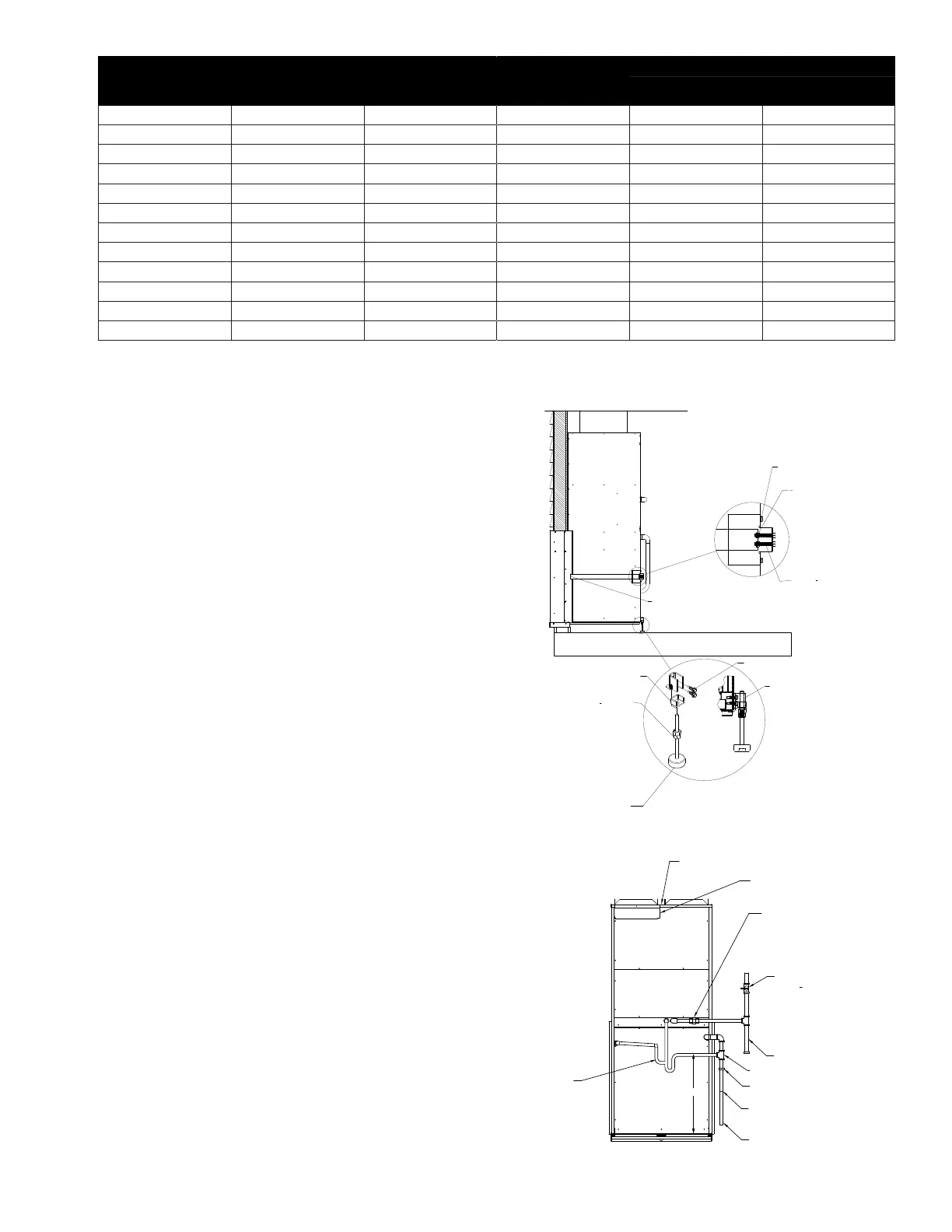
1. With the gas valve and outdoor section access panels removed, connect
the drain trap to the internal drain hoses using the 90 degree barb fittings
provided.
2. Install the ¾ x ¾ x 5/8 tee fitting in the air conditioner drain at the level of
the combustion condensate trap.
3. Complete the furnace drain line by installing a barb fitting into the drain
trap hose.
4. Install a 5/8 vinyl hose between the barb sitting and the tee fitting
installed in the air conditioner drain line. See Figure 5. The furnace
condensate line will self-prime on startup.
Note: The furnace drain and air conditioner condensate drain are open to the
atmosphere which gives pressure equalization on the sewer trap preventing
“double trapping.”
ELECTRICAL CONNECTIONS
The Dynapack unit is approved using copper conductors only. See the unit data
plate for unit minimum circuit ampacity. Size the wire based on the unit circuit
ampacity, type of wire used, and method of wiring, in conduit or open. If the
electrical supply is 208 volt, then do not exceed 2% voltage drop based on the
length of wire run. See the National Electrical Code or the Canadian Electrical
Code for more information.
The typical electrical supply is two phase wires where voltage measured is 208-
230 volts phase to phase. An additional wire for unit grounding is required. See
the unit data plate for the maximum fuse or circuit breaker size. It is recommended
that time delay fuses or a two pole HACR breaker be used in order to prevent
nuisance trips.
Alternately, the Dynapack unit may be wired with one phase wire where the
voltage measured is 208-230 volts phase to neutral. In this case, the phase wire
should be connected to L1 on the contactor. An additional wire for unit grounding
is required.
On 208 volt systems the transformer wiring needs to be changed. Swap the red
transformer wire for the orange wire for 208 volt operation.
A disconnect should be installed next to the unit so the electrical power can be
turned off for servicing or maintenance.
GAS SUPPLY
All Dynapack units are built to operate on natural gas.
Minimum gas supply pressure for purposes of input adjustment:
Minimum Maximum
Natural Gas 5" W.C. * 7" W.C.
*Water Column
GAS PIPING
The Dynapack unit has a ½” pipe connection for the gas line. The size of the gas
piping must be based on the length of the run and not the connection size. See
table 5 for reference pipe sizing.
Consult with the local gas utility or code authority for gas piping installation.
If local codes allow the use of a exible gas appliance connector, always use
a new listed connector. Do not use a connector which has previously serviced
another gas appliance.
The gas piping should contain a manual shut off valve with test port near the
furnace in addition to a drip leg and a ground joint union for servicing. The
test port needs to be upstream of the manual shut off valve for leak testing and
adjusting the supply pressure regulator.
The manual shut off valve must be rated for the gas piping test pressure. If not,
then the shut off valve must be removed from the piping system during testing.
Once the gas piping up to the shut off valve has been tested, the remaining piping
to the unit gas valve must be tested. Do not exceed ½ psig or 14” water column
for this test or the gas valve may be damaged.
RETURN SUPPLY
ACCESS PANEL
TO
CONTROLS
ACCESS PANEL
TO GAS VALVE
AND BURNERS
ACCESS PANEL
TO COMPRESSOR
AND OUTDOOR FAN
DRIP LEG (FIELD SUPPLIED)
MANUAL SHUTOFF VALVE
WITH
1
8
"NPT PLUGGED TAPPING,
ACCESSIBLE FOR TEST GAUGE
CONNECTION (FIELD SUPPLIED)
CONDENSATE DRAIN
GROUND JOINT UNION
(FIELD SUPPLIED)
FILTER DOOR
TRAP
ROUTE TO BUILDING DRAIN
ELECTRICAL POWER ENTRANCE
FRONT VIEW
3/4" X 3/4" X 5/8" TEE
DRAIN TRAP TUBE
18"
Figure 5
#10-24 X 1
1
2
MACHINE SCREW
3
8
-16 HEX NUT
THE LEVELER BRACKET INSTALLS
INTO UNIT BRACKET AND IS HELD
IN PLACE BY THE UNIT WEIGHT
#12 X .75" DRILL SCREWS
(2 PLACES)
LOCATE BRACKET BY INSTALLING
THE TAB UNDER THE UNIT BASE
AND ABOVE THE BASE RAIL.
TINNERMAN CLIP
ATTACH BRACKET TO UNIT
WITH (2) #10 X 1/2" DRILL SCREWS
(2 ON EACH BRACKET)
ENGAGE FLANGE ON WALL SLEEVE
WITH FLANGE ON STRAP. TIGHTEN
MACHINE SCREWS UNTIL BRACKET
CAN BE SECURED TO UNIT WITH
DRILL SCREWS.
Figure 4
WALL SLEEVE
(Nominal)
MAX WALL
THICKNESS
PVC PIPE CUT
LENGTH (Inches)
PIPE LENGTH
EXTENSION FROM
UNIT
WALL SLEEVE STOCK NUMBERS
SHORT LONG
*CW 3 7/8" 27" 6" ---------- ----------
4" 5 7/8" 29" 8" 1741 1736
6" 7 7/8" 31" 10" 1742 1737
8" 9 7/8" 33" 12" 1743 1738
10" 11 7/8" 35" 14" 1744 1739
12" 13 7/8" 37" 16" 1745 1740
14" 15 7/8" 39" 18" 1769 1770
16" 17 7/8" 41" 20" 1771 1772
17" 18 7/8" 42" 21" 1773 1774
18" 19 7/8" 43" 22" ---------- ----------
20" 21 7/8" 45" 24" ---------- ----------
22" 23 7/8" 47" 26" ---------- ----------
TABLE 1
 Loading...