Suburban DynaPack H Series Owner's Manual 10/2017 Rev.4 4
REQUIREMENTS FOR INSTALLATION
Commonwealth of Massachusetts
For all side wall horizontally vented gas fueled equipment installed in every
dwelling, building or structure used in whole or in part for residential purposes,
including those owned or operated by the Commonwealth and where the side
wall exhaust vent termination is less than seven (7) feet above nished grade
in the area of the venting, including but not limited to decks and porches, the
following requirements shall be satised:
1. INSTALLATION OF CARBON MONOXIDE DETECTORS. At the time
of installation of the side wall horizontal vented gas fueled equipment,
the installing plumber or gas tter shall observe that a hard wired carbon
monoxide detector with an alarm and battery back-up is installed on
the oor level where the gas equipment is to be installed. In addition,
the installing plumber or gas tter shall observe that a battery operated
or hard wired carbon monoxide detector with an alarm is installed on
each additional level of the dwelling, building or structure served by
the side wall horizontal vented gas fueled equipment. It shall be the
responsibility of the property owner to secure the services of qualied
licensed professionals for the installation of hard wired carbon monoxide
detectors.
a. In the event that the side wall horizontally vented gas fueled equipment
is installed in a crawl space or an attic, the hard wired carbon monoxide
detector with alarm and battery back-up may be installed on the next
adjacent oor level.
b. In the event that the requirements of this subdivision can not be met at the
time of completion of installation, the owner shall have a period of thirty
(30) days to comply with the above requirements; provided, however, that
during said thirty (30) day period, a battery operated carbon monoxide
detector with an alarm shall be installed.
2. APPROVED CARBON MONOXIDE DETECTORS. Each carbon
monoxide detector as required in accordance with the above provisions
shall comply with NFPA 720 and be ANSI/UL 2034 listed and IAS certied.
3. SIGNAGE. A metal or plastic identication plate shall be permanently
mounted to the exterior of the building at a minimum height of eight (8)
feet above grade directly in line with the exhaust vent terminal for the
horizontally vented gas fueled heating appliance or equipment. The sign
shall read, in print size no less than one half (½) inch in size, “GAS VENT
DIRECTLY BELOW, KEEP CLEAR OF ALL OBSTRUCTIONS”.
4. INSPECTION. The state or local gas inspector of the side wall horizontally
vented gas fueled equipment shall not approve the installation unless,
upon inspection, the inspector observes carbon monoxide detectors and
signage installed in accordance with the provisions of 248 CMR 5.08(2)
(a)1 through 4.
(b) EXEMPTIONS: The following equipment is exempt from 248 CMR
5.08(2)(a)1 through 4:
1. The equipment listed in Chapter 10 entitled “Equipment Not Required
To Be Vented” in the most current edition of NFPA 54 as adopted by the
Board; and
2. Product Approved side wall horizontally vented gas fueled equipment
installed in a room or structure separate from the dwelling, building or
structure used in whole or in part for residential purposes.
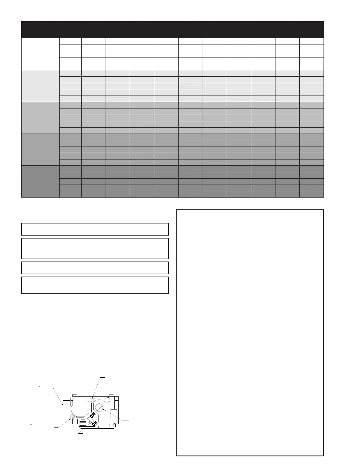
OUTSIDE OF POST.
USE
3
32
" HEX WRENCH
TO OPEN ONE TURN.
TEST HOSE GOES OVER
OUTSIDE OF POST. USE
3
32
" HEX WRENCH TO OPEN
ONE TURN.
INLET
1
2
" NPT
REGULATOR ADJUSTMENT
Figure 6
INDOOR CFM vs STATIC PRESSURE (Dry coil + no air lter)
Model Number
Blower
Speed
0.10" wc 0.15" wc 0.20" wc 0.25" wc 0.30" wc 0.40" wc 0.50" wc 0.60" wc 0.70" wc 0.80" wc
DYPA12AC1A***
LO 497 473 448 424 400 348 296 247 212 160
MED LO 577 562 547 522 497 458 415 357 317 281
MED 757 748 739 716 692 670 635 586 558 521
MED HI 937 920 905 888 872 852 827 790 728 677
HI 1060 1050 1042 1015 977 927 876 824 758 700
DYPA18AC1A***
LO 512 491 469 428 387 320 285 250 213 179
MED LO 596 568 540 522 504 447 415 381 324 291
MED 773 761 748 730 711 675 640 622 586 550
MED HI 972 955 938 927 915 874 850 825 796 766
HI 1108 1091 1074 1057 1039 1002 970 917 868 796
DYPA24AC1A***
LO 504 483 461 420 379 312 252 207 N/R N/R
MED LO 588 560 532 514 496 439 377 320 262 202
MED 765 753 740 722 703 667 622 572 532 482
MED HI 964 947 930 919 907 866 828 782 757 702
HI 1100 1083 1066 1049 1031 994 962 922 882 827
DYPA30AC1A***
LO 490 465 440 415 385 310 225 170 N/R N/R
MED LO 570 540 520 500 476 415 365 310 250 205
MED 768 755 741 732 704 666 621 580 535 500
MED HI 934 922 913 895 873 835 800 760 730 690
HI 1064 1046 1017 1009 995 965 935 900 875 828
DYPA36AC1A***
LO 490 465 440 415 385 310 225 170 N/R N/R
MED LO 570 540 520 500 476 415 365 310 250 205
MED 768 755 741 732 704 666 621 580 535 500
MED HI 934 922 913 895 873 835 800 760 730 690
HI 1064 1046 1017 1009 995 965 935 900 875 828
TABLE 3
CAUTION: Suburban does not recommend the use of ex tubing to make the gas
connections to the unit unless the ex tubing is a high quality stainless certied by
CSA and approved for use by local code.
WARNING! A pipe thread compound resistant to the action of natural gas must be used
on all pipe joints.
WARNING! The gas valve supplied with this furnace is rated at 1/2 psig maximum. Any
higher pressure may rupture the pressure regulator diaphragm and may cause over ring
of the burners and improper burner operation. The over ring may result in the creation of
carbon monoxide which could cause asphyxiation.
WARNING! FIRE OR EXPLOSION HAZARD! Failure to follow the safety warning
exactly could result in serious injury, death, or property damage.
WARNING! Never test for gas leaks with an open ame. Use a commercially available
soap solution made specically for the detection of leaks to check all connections. A re or
explosion may result causing property damage, personal injury, or loss of life.
CONTROL WIRING
The room thermostat should be installed on an interior wall and near the return air
for the unit. It is recommended that a 5 conductor thermostat wire be used in case
the room thermostat needs power from the unit transformer.
The low voltage pigtails for the thermostat wiring must be routed to the outside of
the Dynapack unit for connection. The Dynapack unit contains a second knockout
above the control box for this purpose. The National Electrical Code requires
that low voltage wiring be kept separate from high voltage wiring and cannot be
routed through the same knockout or conduit. Local codes may also require that
an electrical box be installed on the low voltage knockout to contain the electrical
connections.
Follow the thermostat manufacturers instructions for mounting and wiring. The
low voltage is grounded inside the unit control box. See Figure 8.
 Loading...