Left
Right
Exhaust
and
Model
Front
Side Side
Top
Bottom
Back
Intake
Tube
SF-20Q 1"
O" O" O" O"
O"
3/8"
SF-25Q
1"
O" O" O" O"
O"
3/8"
SF-30Q
1"
O"
O" O" O" O"
3/8"
SF-35Q
1"
O"
O" O" O" O"
3/8"
SF-42Q
1"
2"
2" 1"
O"
O"
3/8"
-NOTE-
O"
MEANS
TO SPACER
BUMPS
CLEARANCE
FROM
D
UCTS
TO
COMBUSTIBLE
MATERIAL
- 1
/4"
(See
Figure
3)
TABLE
2
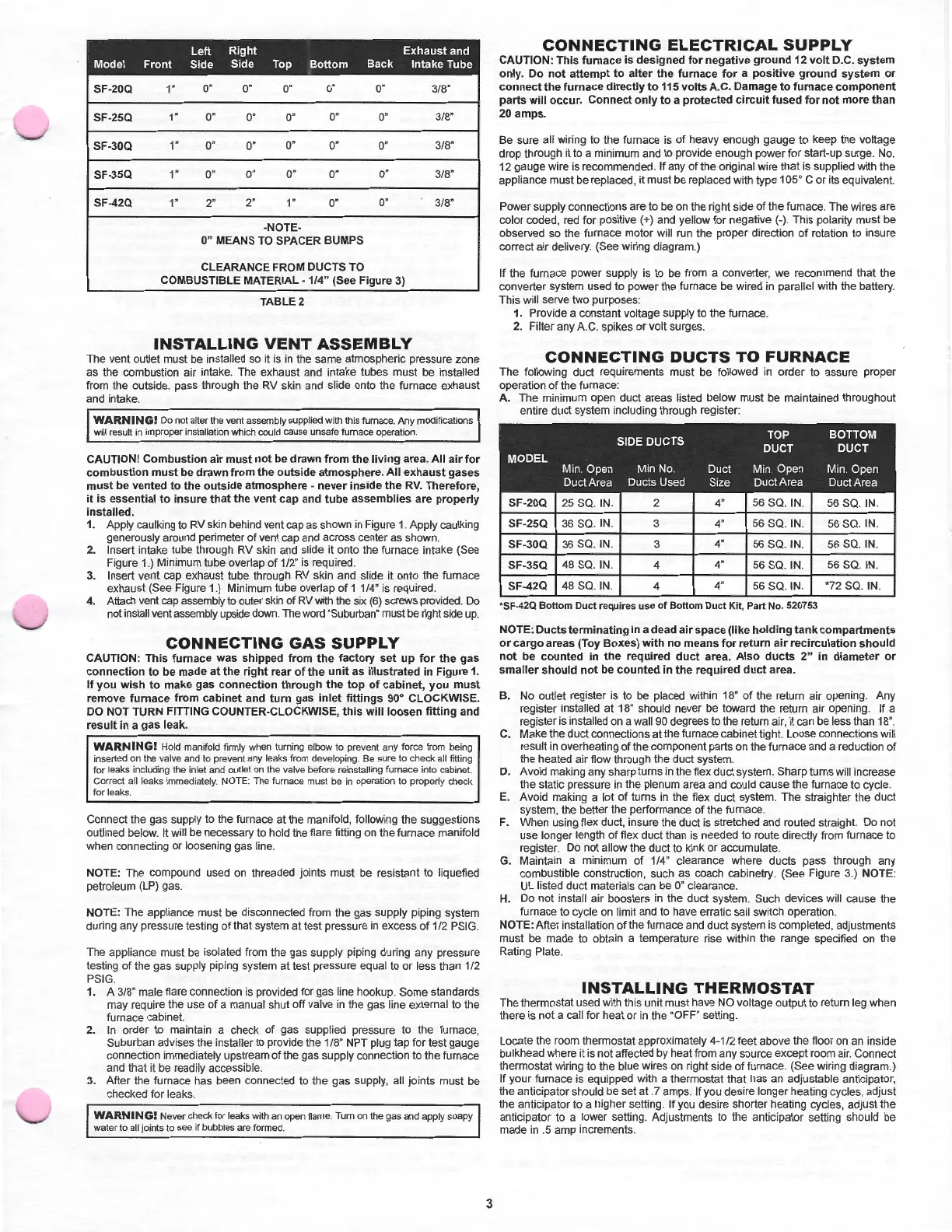
INSTALLING
VENT
ASSEMBLY
The
vent outlet must be installed so it is
in
the
same
atmospheric pressure zone
as the combustion air intake. The exhaust and intake tubes
must
be installed
from the outside, pass through the RV skin and slide onto the furnace exhaust
and intake.
WARNING!
Do not alter the vent assembly supplied with this furnace. Any modifications
will result
in
improper installation which could
ca
u
se
unsafe furnace operation.
CAUTION!
Combustion
air
must
not
be
dra
wn
from
the
living
area.
All
air
for
combustion
must
be
drawn
from
the
outsid
e
atmosphere.
All
exhaust
gases
must
be
vented
to
the
outs
ide
atmosphere
-
never
inside
the
RV.
Therefore,
it
is
essential
to
insure
that
the
vent
cap
and
tube
assemblies
are
properly
installed.
1. Apply caulking to RV skin behind vent cap as shown
in
Figure 1. Apply caulking
generously around perimeter
of
vent cap and across center as shown.
2. Insert intake tube through RV skin and
sl
ide it onto the furnace intake (See
Figure 1.) Minimum tube overlap
of
1/2"
is
required.
3.
Insert vent cap exhaust tube through RV skin and slide it onto the furnace
exhaust (See Figure 1.) Minimum tube overlap
of
1 1/4" is required.
4. Attach vent cap assembly to outer skin of RV with the six
(6)
screws provided. Do
not install vent assembly upside down. The wo
rd
"Suburban" must be right side up.
CONNECTING
GAS
SUPPLY
CAUTION:
This
furnace
was
shipped
from
the
factory
set
up
for
the
gas
connection
to
be
made
at
the
right
rear
of
the
unit
as
illustrated
in Figure
1.
If
you
wish
to
make
gas
connection
throu
gh
the
top
of
cabinet,
you
must
remove
furnace
from
cabinet
and
turn
gas
inlet
fittings
90°
CLOCKWISE.
DO NOT TURN FITTING COUNTER-CLOCKWISE,
this
will
loosen
fitting
and
result
in
a
gas
leak.
WARNING!
Hold manifo
ld
firmly when tu
rn
in
g elbow to prevent any force from being
inserted on the
valve and to
pre
vent any leaks from developi
ng.
Be
sure to check all fitting
for leaks includi
ng
the inlet a
nd
outlet on the valve befo
re
reinstalling furnace into cabinet.
Correct a
ll
leaks immedi
at
e
ly.
NOTE: The furnace must be in operation to properly check
for
leaks.
Connect the gas supply to the furnace
at
the manifold, following the suggestions
outlined below. It will be necessary to hold the flare fitting
on
the furnace manifold
when connecting or loosening gas line.
NOTE: The compound used
on
threaded joints must be resistant to liquefied
petroleum (LP) gas.
NOTE: The appliance must be disconnected fr
om
the gas supply piping system
during any pressure t
est
ing
of
that system
at
te
st pressure in excess
of
1 /2 PSIG.
The appliance must be isolated from the gas supply piping during any pressure
testing
of
the gas supply piping system
at
test pressure equal to or less than 1/2
PSIG.
1. A 3/8" male flare connection is provided for gas line hookup.
Some
standards
may require the use
of
a manual shut
off
valve
in
the gas line external to the
furnace cabinet.
2.
In
order to maintain a check
of
gas supplied pressure to the furnace,
Suburban advises the installer to provide the 1/8" NPT plug tap for test gauge
connection immediately upstream
of
the gas supply connection to
the
furnace
and that it be readily accessible.
3.
After the furnace has been connected to t
he
gas supply, all
joints
must be
checked for leaks.
WARNING!
Never check for leaks wi
th
an open
fl
ame. Turn on the gas and apply soapy
water to
all joints to see if bubbles are formed.
3
CONNECTING
ELECTRICAL
SUPPLY
CAUTION:
Th
is
furnace
is
designed
for
negative
ground
12
volt
D.C.
system
only
.
Do
not
attempt
to
alter
the
furnace
for
a
positive
ground
system
or
connect
the
furnace
directly
to
115
volts
A.C
.
Damage
to
furnace
component
parts
will
occur.
Connect
only
to
a
protected
circuit
fused
for
not
more
than
20
amps.
Be
sure all wiring to the furnace is
of
heavy enough
gauge
to keep the voltage
drop through it to a minimum and to provide enough
power
for start-up surge. No.
12 gauge wire is recommended. If any
of
the
original wire that is supplied with the
appliance must be replaced, it must be replaced with type 105° C
or
its equivalent.
Power
supply connections are to be on the right side
of
the
furnace.
The
wires are
color coded, red for positive (+) and yellow for negative (-
).
This polarity
must
be
observed so the furnace motor will run the proper direction
of
rotation to insure
correct air delivery. (See wiring diagram.)
If the furnace power supply is to be from a converter,
we
recommend that the
converter system used to power the furnace be wired
in
parallel with the battery.
This will serve two purposes:
1. Provide a constant voltage supply to the furnace.
2. Filter any A.G. spikes
or
volt surges.
CONNECTING
DUCTS
TO
FURNACE
The
following duct requirements
must
be followed
in
order
to assure proper
operation
of
the furnace:
A.
The
minimum open duct areas listed below must be maintained throughout
entire duct system including
through register:
SIDE DUCTS
TOP
BOTTOM
DUCT
DUCT
MODEL
Min Open Min No
Duct
Min Open Min Open
Duct Area Ducts Used Size Duct
Area
Duct Area
SF-20Q 25 SQ.
IN
. 2 4" 56 SQ. IN. 56 SQ.
IN
.
SF-25Q 36 SQ.
IN
. 3 4" 56 SQ.
IN
. 56 SQ.
IN
.
SF-30Q
36 SQ.
IN
.
3
4" 56
SQ
.
IN
.
56 SQ.
IN
.
SF-35Q
48 SQ. IN.
4
4" 56 SQ.
IN.
56 SQ.
IN
.
SF-42Q 48 SQ.
IN
. 4 4" 56 SQ. IN. *72 SQ. IN.
•SF-420
Bottom
Duct
requires
use
of
Bottom
Duct
Kit
, Part No. 520753
NOTE:
Ducts
terminating
in
a
dead
airspace
(like
holding
tank
compartments
or
cargo
areas
(Toy
Boxes)
with
no
means
for
return
air
recirculation
should
not
be
counted
in
the
required
duct
area.
Also
ducts
2"
in
diameter
or
smaller
should
not
be
counted
in
the
required
duct
area.
B. No outlet register is to be placed within 18"
of
the return air opening. Any
register installed at 18" should never be toward the return air opening. If a
register is installed on a wall 90 degrees to the return air, it can be less than 18
".
C.
Make
the
duct connections at the furnace cabinet tight. Loose connections will
result in overheating
of
the component parts on the furnace and a reduction
of
the heated air flow through the duct system.
D.
Avoid making any sharp turns in the flex duct system. Sharp turns will increase
the
static pressure in the plenum area and could cause the furnace to cycle.
E. Avoid ma
ki
ng a lot
of
turns in the flex
duct
system.
The
straighter the
duc
t
system, the better the performance
of
the furnace.
F.
When using flex duct, insure the duct is stretched and routed straight. Do not
use longer length
of
flex duct than is needed to route directly from furnace to
register. Do not allow the duct to kink or accumulate.
G.
Maintain a minimum
of
1/4" clearance where ducts pass through any
combustible construction, such
as
coach cabinetry. (See Figure 3.) NOTE:
UL listed duct materials can be O" clearance.
H.
Do
not
install
air
boosters in the duct system. Such devices will cause the
furnace to cycle on limit and to have erratic sail switch operation.
NOTE:
After
installation
of
the furnace and duct system is completed, adjustments
must be
made
to obtain a temperature rise within the range specified on the
Rating Plate.
INSTALLING
THERMOSTAT
The thermostat used with this unit
must
have NO voltage output to return leg when
there is
not
a call for heat or
in
the "OFF" setting.
Locate the room thermostat approximately
4-1
/2 feet above the floor on an inside
bulkhead where it is not affected by heat from any source ex
cept
room air. Connect
thermostat wiring to the blue wires on right side
of
furnace. (
See
wiring diagram.)
If
your
furnace is equipped with a thermostat that has an adjustable anticipator,
the anticipator should be set
at
. 7 amps. If you desire longer heating cycles, adjust
the anticipator to a higher setting. If you desire shorter heating cycles, adjust the
anticipator to a lower setting. Adjustments to the anticipator setting should be
made
in
.5 amp increments.

 Loading...