In the U.S.A., the installation of the furnace must be in accordance with local
codes and regulations. In the absence of local codes and regulations, refer to the
latest edition of:
1. Standard for Recreational Vehicles NFPA 1192.
2. National Fuel Gas Code ANSI Z223.1/NFPA 54.
3. Furnace must be electrically grounded in accordance with the latest edition of
the National Electrical Code NFPA 70.
In Canada, the furnace must be installed in accordance with:
1. Standard CSA Z240.0.2-08 Recreational Vehicles.
2. CSA Standard Z240.6.2-08 C22.2 NO.148-08 Electrical Requirements for
Recreational Vehicles.
3. Standard Z240.4.2-08 Installation Requirements for Propane Appliances and
Equipment in Recreational Vehicles.
4. CAN/CGA-B149 Installation Codes.
5. Any applicable local codes and regulations.
This unit is equipped with an electric igniter device that has an energy consumption
of .1 amp @ 12 volts D.C.
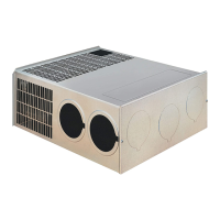
RETURN AIR
There are two (2) methods described below for installing the furnace. Regardless
of the method you choose, we require that a permanent opening be provided in
the interior cabinetry of the coach directly in front of the furnace. The opening must
allow for free, unobstructed removal of the furnace. This opening may be used as
a means of providing circulating return air to the furnace. Other openings may be
used as well.
It is important that adequate return air be provided to assure normal heating and
operation of the furnace. Failure to provide the minimum return air will cause
erratic furnace cycling. Refer to the chart shown below for minimum return air
requirements.
NOTE: Return air must be from within the living area of the coach.
NOTE: RV’s that have a wall of separation to a cargo area (Toy Box) to transport
internal combustion engine vehicles must not have return air openings from this
area.
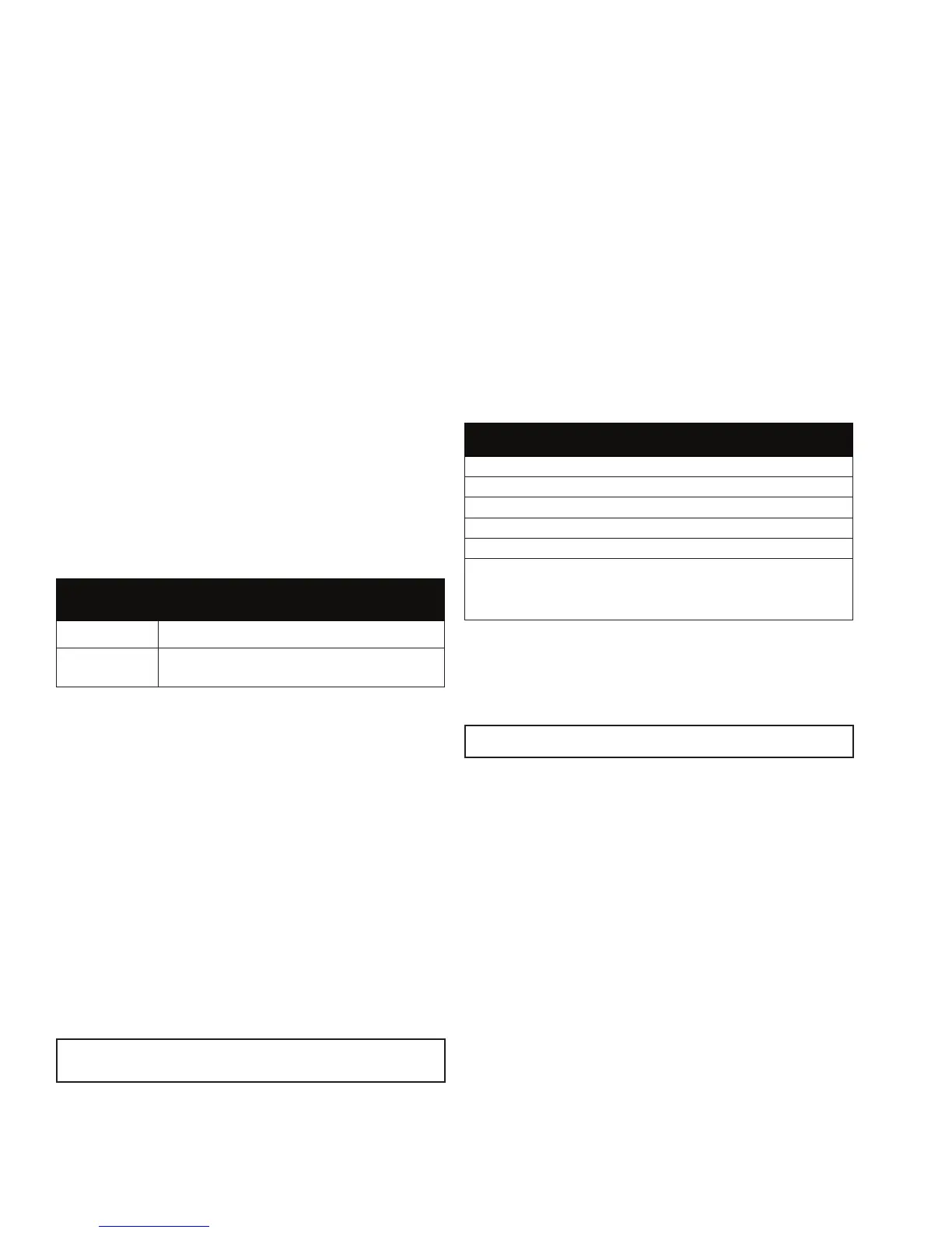
Return Air Requirements
Model Minimum Free (unobstructed) Area
SF-20/25/30/35FQ 55 Sq. In.
SF-42FQ
142 Sq. In.*
*may be reduced to 88 sq. in. min. if 5 ducts are used.
TABLE 1
INSTALLING THE FURNACE
NOTE: Before installing the furnace “X” dimension as illustrated in Figure 2 must
be determined.
1. Locate the furnace near lengthwise center of the coach.
2. Choose a location for installation out of the way of wires, pipes, etc., which
might interfere with the installation. Adhere to the minimum clearances from
the cabinet to combustible construction as listed in Table 2. Refer to Figure 3
for illustration of furnace clearances.
NOTE: Side and top clearances may be “0” for through the wall installations up to
a maximum of 3” wall thickness. (See Figure 1.)
3. When an appliance is installed directly on carpeting, tile or other combustible
material, other than wood ooring, the appliance shall be installed on a metal
or wood panel extending the full width and depth of the appliance. If preferred,
the carpeting, tile or combustible materials, other than wood may be cut
away the full length and depth of the appliance plus the appliance minimum
clearances to combustibles. (See Table 2.)
4. Determine “x” dimension as shown in Figure 2. The tubes supplied with the
furnace will accommodate an installation range for “x” from 1-1/2” - 3” If “x”
dimension is less than 1-1/2” or greater than 3”, then special vent tubes as
charted in Figure 2 must be ordered.
WARNING! Do not alter, cut or otherwise modify the vent tubes as supplied by Suburban.
Doing so could result in inadequate intake of combustion air or improper venting of furnace
exhaust.
5. After determining “x” dimension, complete the furnace installation as follows:
A. IF INSTALLED DIRECTLY AGAINST OUTER SKIN OR “X” DIMENSION IS
0 - 1-1/2”
1. Vent Kit 520767 must be ordered. Do not cut or alter the vent tubes supplied
with the furnace.
2. Cut an opening through the inner wall 17-3/4 x 8”. This will allow the rear of
the furnace to be installed against the outer skin of the coach. (See Figure 1.)
3. Cut two 2-1/4” diameter holes through the outer skin of the coach, as shown
in Figure 1.
4. Put furnace in place, making sure that rear of furnace cabinet is as close to
outer skin of coach as possible and still assure proper vent tube overlap. (See
Installing Vent Assembly.) Secure furnace to cabinet. (See Figure 1.)
5. Secure furnace to the oor using two (2) hole provided in the furnace cabinet.
(See Figure 1.)
6. Install vent assembly. (See instructions for installing vent.)
B. IF NOT INSTALLED AGAINST OUTER SKIN AND “X” DIMENSION
GREATER THAN 1-1/2”
1. Determine “x” dimension as illustrated in Figure 2. Tube length for “x”
dimension are charted. Special tubes, if needed, must be ordered.
2. Locate center lines for exhaust and intake tubes as shown Figure 1. Cut two
2-3/4” diameter holes through coach wall for exhaust and intake. (See Figure 2.)
3. Put furnace in place and secure furnace to cabinet.
4. Secure furnace to the oor using the two (2) holes provided in the furnace
cabinet. (See Figure 1,)
5. Install vent assembly. (See instructions for Installing Vent.)
6. Reinstall cabinet front.
Left Right Exhaust and
Model Front Side Side Top Bottom Back Intake Tube
SF-20FQ 1” 0” 0” 0” 0” 0” 3/8”
SF-25FQ 1” 0” 0” 0” 0” 0” 3/8”
SF-30FQ 1” 0” 0” 0” 0” 0” 3/8”
SF-35FQ 1” 0” 0” 0” 0” 0” 3/8”
SF-42FQ 1” 2” 2” 1” 0” 0” 3/8”
-NOTE-
0” MEANS TO SPACER BUMPS
CLEARANCE FROM DUCTS TO
COMBUSTIBLE MATERIAL - 1/4” (See Figure 3)
TABLE 2
INSTALLING VENT ASSEMBLY
The vent outlet must be installed so it is in the same atmospheric pressure zone
as the combustion air intake. The exhaust and intake tubes must be installed
from the outside, pass through the RV skin and slide onto the furnace exhaust
and intake.
WARNING! Do not alter the vent assembly supplied with this furnace. Any modications
will result in improper installation which could cause unsafe furnace operation.
CAUTION! Combustion air must not be drawn from the living area. All air for
combustion must be drawn from the outside atmosphere. All exhaust gases
must be vented to the outside atmosphere - never inside the RV. Therefore, it is
essential to insure that the vent cap and tube assemblies are properly installed.
1. Apply caulking to RV skin behind vent cap as shown in Figure 1. Apply
caulking generously around perimeter of vent cap and across center as
shown.
2. Insert intake tube through RV skin and slide it onto the furnace intake (See
Figure 2.) Minimum tube overlap of 1/2” is required.
3. Insert vent cap exhaust tube through RV skin and slide it onto the furnace
exhaust (See Figure 2.) Minimum tube overlap of 1 1/4” is required.
4. Attach vent cap assembly to outer skin of RV with the six (6) screws provided.
Do not install vent assembly upside down. The word “Suburban” must be right
side up.
CONNECTING GAS SUPPLY
Connect the gas supply to the furnace at the manifold, following the suggestions
outlined below. It will be necessary to hold the are tting on the furnace manifold
when connecting or loosening gas line.
NOTE: The compound used on threaded joints must be resistant to liqueed
petroleum (LP) gas.
NOTE: The appliance must be disconnected from the gas supply piping system
during any pressure testing of that system at test pressure in excess of 1/2 PSIG.
2
 Loading...