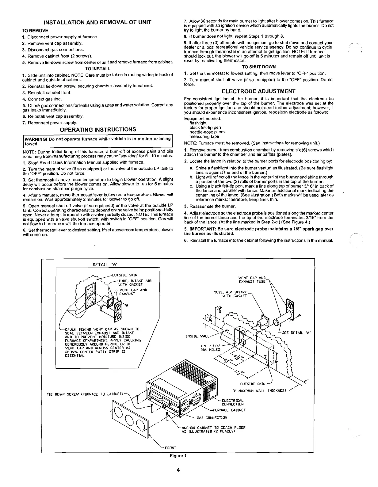
INSTALLATION AND REMOVAL OF UNIT
TO REMOVE
I.
Disconnect power supply at furnace.
2.
Remove vent cap assembly.
3.
Disconnect gas connections.
4.
Remove cabinet front
(2
screws).
5.
Remove tiedown screw from center of unit and remove furnace from cabinet.
TO INSTALL
I.
Slide unit into cabinet. NOTE: Care must be taken in routing wiring to backof
cabinet and outside of cabinet.
2.
Reinstall tiedown screw. securing chamber assembly to cabinet.
3.
Reinstall cabinet front.
4.
Connect gas line.
5.
Check gasconnections for leaks using a soap and water solution. Correct any
gas leaks immediately.
6.
Reinstall vent cap assembly.
7.
Reconnect power supply.
OPERATING INSTRUCTIONS
WARNING1 Do not operate furnace while vehicle is in motion or being
towed.
NOTE: During initial firing of this furnace, a burn-off of excess paint and oils
remaining from manufacturing process may cause "smoking" for
5
-
10
minutes.
I.
Stop! Read Users Information Manual supplied with furnace.
7.
Allow 30 seconds for main burner to light after blower comes on. This furnace
is equipped with an ignition device which automatically lights the burner. Do not
try to light the burner by hand.
8.
If burner does not light, repeat Steps
1
through 8.
9.
If after three (3) attempts with no ignition, go to shut down and contact your
dealer or a local recreational vehicle service agency. Do not continue to cycle
furnace through thermostat In an attemot to aet ian~tion. NOTE: If furnace
-
~
should lock out, the blower will go off
in'5
miiutes and remain off until unit is
reset by reactivating thermostat.
TO SHUT DOWN
I.
Set the thermostat to lowest setting, then move lever to "OFF position.
2.
Turn manual shut off valve (if so equipped) to the 'OFF" position. Do not
force.
ELECTRODE ADJUSTMENT
For consistent ignition of the burner, it is important that the electrode be
positioned properly over the top of the
burner. The electrode was set at the
factory for proper ignition and should not need further adjustment; however, if
you should experience inconsistent ignition, reposition electrode as follows:
Equipment needed:
flashlight
black felt-tip pen
needle-nose pliers
measuring tape
NOTE: Furnace must be removed. (See instructions for removing unit.)
I.
Remove burner from combustion chamber by removing six
(6)
screws which
attach the burner to the chamber and air baffles (plates).
2.
Locate the lance in relation to the burner ports for electrode positioning by:
2.
Turn the manual valve (if so equipped) or the valve at the outside LP tank to
a. Shine a flashlight into the burner venturi as illustrated. (Be sure flashlight
the "OFF" position. Do not force. lens is against the end of the burner.)
3.
Set
thermostat above room
temperature
to
begin
blower
A
slight
b. Light will reflect off the lance in the venturi of the burner and shine through
a portion of the
two (2) rolls of burner ports in the top of the burner.
delay will occur before the blower comes on. Allow blower to
run for
5
minutes
c.
Using
a
black
felt-tip
pen,
mark
a
line
along
top
of
burner
311
6m
in
back
of
for combustion chamber purge cycle.
the lance and parallel with lance. Make an additional mark indicating the
.
4.
After
5
minutes, move thermostat lever below room temperature. Blower will
center line of the lance. (See illustration.) Both marks will be used later as
remain on. Wait approximately 2 minutes for blower to go off. reference marks; therefore, keen lines thin.
-
-
r
5.
Open manual shut-off valve (if so equipped) or the valve at the outside LP
3.
Reassemble the burner.
tank.'~orrect operating characteristics depend on the valve being positioned fully
open. Never attempt tooperate with a valve partially closed. NOTE:
This furnace
4.
Adjust electrode
SO
the electrode probe is positioned along the marked center
is
eauiooed with a valve shut-off switch. with switch in "OFF position. Gas will
lineof !he burner lance
,
.
. .
.
and
.
.
the tip of the electrode terminates
3/16"
from the
not flow'to burner nor will the furnace operate.
baa ot the lance. (At tne llne marked in Step 2c.) (See Figure
4.)
6.
Set thermostat leverto desired sett~ng. If set above room temperature, blower
5-
IMPORTANT: Be sure electrode probe maintains a
118"
spark gap over
will
come on.
the burner as illustrated.
6.
Reinstall
the furnace ~nto the cabinet following the instructions in the manual.
 Loading...


