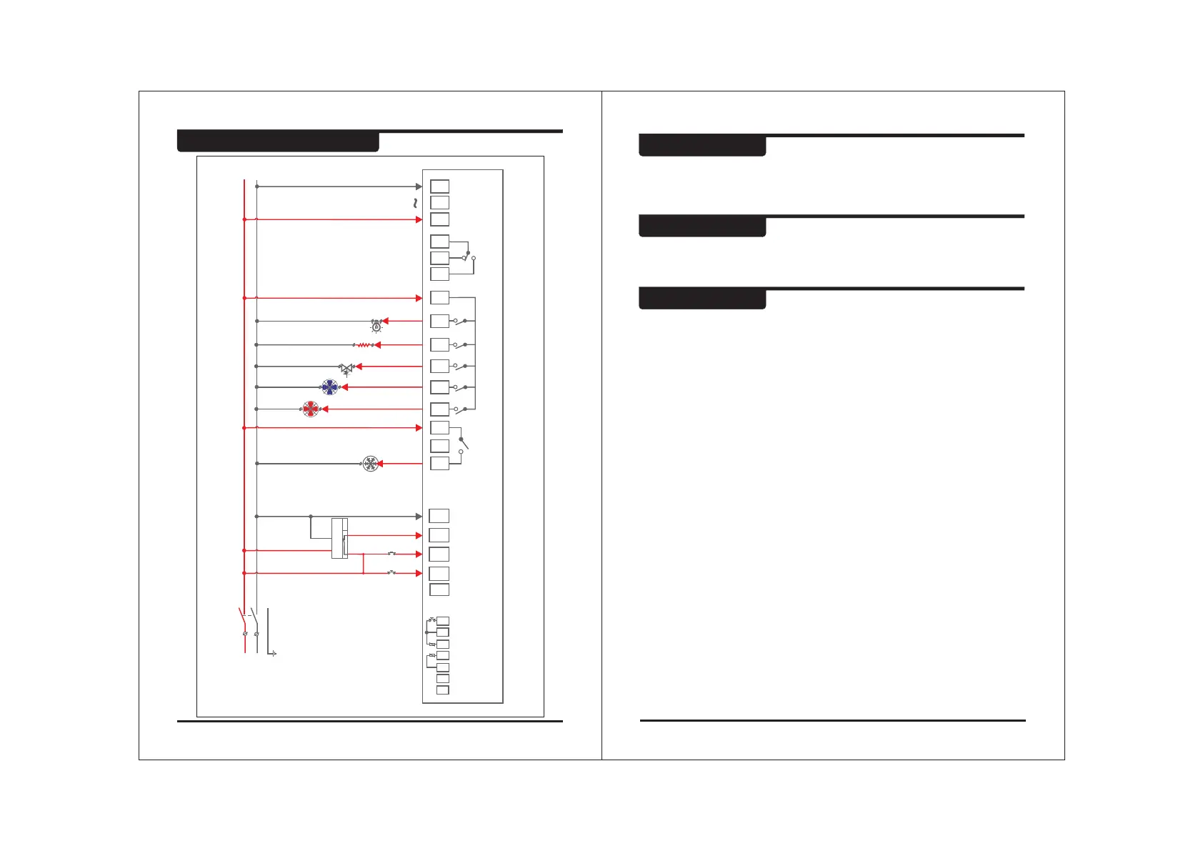
Suggested wiring Diagram
WIRING : The probe and its corresponding wires should never be installed
in a conduit next to control or power supply lines. The electrical wiring
should be done as shown in the diagram. The power supply circuit should
be connected to a protection switch. The terminals admit wires of upto
2.5sq mm.
WARNING : Improper wiring may cause irreparable damage and personal
injury. Kindly ensure that wiring is done by qualified personnel only.
Maintenance : Cleaning : Clean the surface of the controller with a soft
moist cloth. Do not use abrasive detergents, petrol, alcohol or solvents.
Controller
Controller should be installed in a place protected by vibration, water and
corrosive gasses and where ambient temperature does not exceed the values
specified in the technical data.
Probe
To give a correct reading, the probe must be installed in a place protected from
thermal influences, which may affect the temperature to be controlled.
17 18
CRC1200 CRC1200
LP
Phase IN
Phase OUT
17
18
19
HPLP
SPPR
N
DIGITAL INPUTS
16
HEATER
1
12
10
4
LVM
EVAPORATOR
CONDENSOR
LSV
LAMP
HP
COMP
EVAP
LSV
HEAT
LAMP
L N
NO
C
NO NO
CC NC
NO NO NO NO
COND.
(Optional)
L
1
2
MCB1
N
COMPRESSOR
13 11
9
7
12
10
8
15 6
5
4
3
1
230V
ALARM
COIL
PROBE
ROOM
PROBE
+
RS485
25
23
24
22
26
21
DOOR
INPUT
27
-
Caution