Read the enclosed safety instructions, appendix 39 230 ..!
Erection instructions appendix 39 328 ..!
1. Rotofera: Technical data
2. Flexible shaft
3. Start-up procedures:
3.1
Set the operating speed
3.2
Connect the flexible shaft
3.3
Connect the SAK safety clutch
3.4
Connect toolholders
3.5
Start-up with SAK
4. Accessories: FH10, WI10, BSG10, FSM
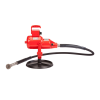
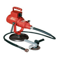
1. Rotofera
F=base plate STM=trolley mounted HM=hanging attachment
Machine elements: See Fig. A
A1 On/Off switch A3 Speed indicator A5 Excenter
A2 Retention pin A4 Speeds A6 Motor shaft
Technical data
Power input / output three - phase 1'000 / 750 W
Power input / output single - phase 800 / 550 W
Insulation protection class IP44
Voltage (see spare parts list) Various
Ground fault protection : Used for tools
with water feed or in humid environments. 45 V
No load speeds 50 Hz 60 Hz
12' 000 14' 400 RPM
8' 000 9' 600
5' 700 6' 800
7-speed gear box 3' 200 3' 800
2' 100 2' 500
1' 600 1' 900
850 1' 000
Sound pressure level CEN/TC 255 N 79 81 dB (A)
Flexible shaft connection DIN 10 =M10 see A6
For flexible shaft types: NA 10 DIN 10 / G28 see B2 B8
(see catalogue) NA 12 DIN 10 / G28
Vibration values ISO/DIS 8662-4
Toolholder type: Test plate: Measured value: Excenter stage:
FH10 ø 80 x 10 < 2,5 m/s
2
12' 000 RPM
WI10 ø 50 x 6 < 2,5 m/s
2
12 '000 RPM
BSG 10 ø 100 x 25 < 2,5 m/s
2
5' 700 RPM
FSM 1:1 ø 180 x 6 < 2,5 m/s
2
8' 000 RPM
Maintenance
• Store machine in a dry, clean place.
• Cooling air ports must be kept free of obstructions.
• Unplug before performing any maintenance work.
• Change gear grease every 12 months. Your SUHNER Service Centre
can perform this work quickly and efficiently.
• Check connecting cables regularly. Damaged cables must be replaced
under all circumstances.
• Repairs may only be performed by a qualified electrician Accidents
could otherwise occur for the operator.
• Complaints can only be accepted if the machine is returned unopened.
2. Flexible shaft
See Fig. B
B4 Casing
Machine elements:
B5 Core
B1 M10 threaded coupling B6 Driving pin
B2 DIN 10 casing coupler B7 Spring-loaded pin
B3 Spring-loaded pin B8 G28 casing coupler
Type: NA10 DIN 10 / G28, permissible operating speed 15' 000 RPM
Type: NA12 DIN 10 / G28, permissible operating speed 12' 000 RPM
Maintenance
• Store flexible shaft in a dry, clean place.
• If used daily: Re-grease once monthly. Remove core
B5
from casing
B4
. Remove shaft grease. Lightly apply SUHNER shaft grease to core
B5
. Order No. for 1 kg can : 904 832.
• New shafts or newly greased shafts require running-in.
• Clean casing coupler
B2 B8
before use. Worn casing couplers lead to
increased vibration and noise. The casing
B4
must then be replaced
(see spare parts list).
3
.
1
Set the operating speed
(Excenter switch)
See Fig. A
• Only change speed when machine is switched off.
A1
Wait until gears
are completely motionless. Unplug power supply.
• Ensure that the desired speed
A4
is permissible for the tool and
toolholder used.
1. Remove retention pin
A2
.
2. Turn excenter
A5
clockwise until it reaches the limit stop. Release
retention pin
A2
. All speeds must be visible in this position.
3. Move excenter
A5
axially until the correct
4. operating speed
A4
is positioned in the speed indicator
A3.
5. Turn excenter
A5
all the way to the left.
6. Retention pin
A2
must
click
audibly into place.
7. Ensure that the correct operating speed is positioned directly and
centrally in the speed indicator A3. If the retention pin does not click
into place, or the selected speed is not displayed in the center, the
procedure must be repeated from Step 1 .
• Attention : In case the machine is operated in one gear position only -
one must at least once a week switch through all positions for a brief
period in order to redistribute the grease for long gear service life.
(run without flex.Shaft and handpiece)
3
.
2
Connect the flexible shaft
to the motor
See Figs. A + B
1. Insert pin in retention hole.
2. Slightly withdraw threaded coupling
B1
from casing coupler
B2
.
3. Insert second pin through transverse hole in threaded coupling
B1
and
4. Fasten tightly onto the motor shaft
A6
.
5. Remove pins.
6. Insert casing coupler
B2
completely into excenter hole
A5
.
7. Depress spring-loaded pin
B3
and completely insert casing coupler
B2
.
8. Spring-loaded pin
B3
must
click
audibly into place in the retention
hole. Ensure that spring-loaded pin
B3
has locked firmly into place. If
necessary, move/rotate casing coupler
B2
until spring-loaded pin
B3
clicks into place.
3
.
3
Connect the SAK safety clutch
(accessory)
See Fig. C
Machine elements:
C1 Retention hole C3 Locking pin C5 Driving pin
C2 Safety lever C4 Spring-loaded pin
Use the Type SAK G28 safety clutch to protect operator from accidental
start-up.
1. Insert casing coupler
B8
into tool connection.
2. Depress spring-loaded pin
B7
and completely insert casing
coupler
B8
.
3. Spring-loaded pin
B7
must
click
audibly into place in retention hole
C1
. Ensure that spring-loaded pin
B7
has locked firmly into place. If
necessary, move/rotate casing coupler
B8
until spring-loaded pin
B7
clicks into place.
3
.
4
Connect toolholders
See Fig. C
The connection of toolholders corresponds to the procedure described
in Item 3.3.
Note: Toolholders WI10, BSG10 and FSM can be rotated on the casing
coupler for easier handling.
3
.
5
Start-up with SAK safety clutch ( deadman switch)
See Fig. D
Only with machine in OFF position !
1. Depress locking pin
C3
.
2. Completely depress safety lever
C2
. If necessary, move to starting
position by turning the working spindle
D1
and repeatedly depressing
safety lever
C2
.
• Attention : The powerfull machine develops a heavy torque when
switched-on. Thus secure yourself in a rigid position and hold on to
the handpiece.
• Switch on drive motor
A1
.
• Switch off by releasing lever
C2
. Torque transmission to the toolholder
is interrupted. Locking pin
C3
protects from automatic start-up.
• Switch machine off in order to return safety lever
C2
to starting
position!
GB
 Loading...