Document No. 8128000560
Software Revision – N1B (07 Oct 04)
7-78
RT-9000 B
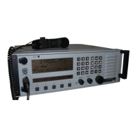
Figure 7.3.4.25 ALE ‘NET CALL’ - Initiating Station Display
At the end of the NET CALL Transmission, the RT-9000 B will revert to Receive scanning and listen for
Network responses. If the NET CALL transmission was heard by other stations in the Network, their
responses will begin to appear on the Operational Display as shown in Figures 7.3.4.26 and 7.3.4.27 and in
their pre-determined time slots (approximately 2 seconds apart). The RT-9000 B supports multiple-network
capability and will append the RT-9000 B ’s local ALE Network Number where the responding station’s CALL
ID resides to the “NR” Operation Indicator.
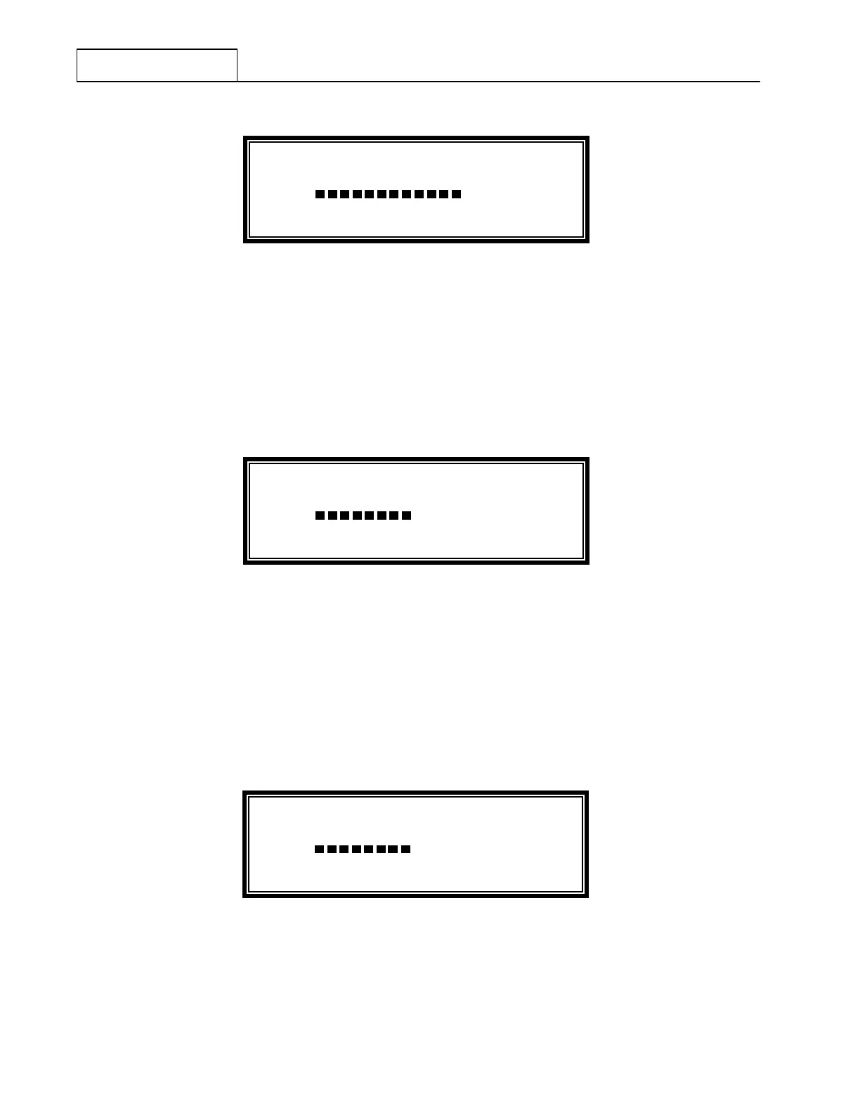
In this example, NRXXSUN2 H XX = The RT-9000 B Network Number in which the Responding
station’s CALL ID, SUN2 is contained.
Figure 7.3.4.26 ALE ‘NET CALL’ – Initiating Station - Response Display (from SUN2)
Figure 7.3.4.27 shows the same type of “Net Response” (NR) information as shown in Figure 7.3.4.26, except
that it shows a different Station is responding to the same NET CALL transmission.
In this example, NRXXSUN3 I XX = The RT-9000 B Network Number in which the Responding
station’s CALL ID, SUN3 is contained.
Figure 7.3.4.27 ALE ‘NET CALL’ – Initiating Station - Response Display (from SUN3)
RC
MHZ
FUNCTION/
STATUS
CH 0314.21200
NR
XSUN2 H
METER
S3 S6 S9 +20 +40 +60
RC
MHZ
FUNCTION/
STATUS
CH 0314.21200
NR
XSUN3 I
METER
S3 S6 S9 +20 +40 +60
20 60 100 150 FWD
RC
MHZ
FUNCTION/
STATUS
CH 0314.21200
CALLING NET STATIONS
XMT
METER
S3 S6 S9 +20 +40 +60
20 60 100 150 FWD
 Loading...