Document No. 8128000560
Software Revision – N1B (07 Oct 04)
7-10
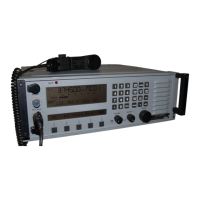
RT-9000 B
2 FAULT INDICATOR
This Red indicator is lit if a ‘FAULT’ condition is detected in the RT-9000 B Transceiver. Check the installation
and proceed to the section on BITE (Built-In-Test-Equipment), located in section 7.3.3.1 of this manual.
3 OPERATIONAL DISPLAY
This Liquid Crystal Display (LCD), provides a variety of information required to operate the equipment.
Information is displayed in four primary areas of the display as indicated in Figure 7.3.1.2.
Frequency Information
Channel
Information
Meter Information
Function & Status Information
FIG 7.3.1.2 RT-9000 B Operational Display - Information Location
4 FUNCTION KEYS
This group of twelve (12) keys is used to control the primary operating functions of the RT-9000B
Transceiver such as Mode selection, Channel selection, Channel loading, AGC characteristic selection,
Local/Remote operation, Power Output level selection, Panel Illumination, Coupler Tune command, and
manual tuning.
5 MANUAL TUNING CONTROL
This control is used to control manual tuning of the RT-9000 B Transceiver frequency or channel selection.
Actual frequency setting or channel selection is indicated in the Operational Display.
6 FREQUENCY/CHANNEL ENTRY KEYS
This group of twelve (12) numeric keys is primarily used for frequency information entry. This keypad may be
used to enter, select, or load a specific operating frequency or Channel Number. This keypad may also be
used to enter other numerical settings and parameters.
 Loading...