The Brighter Choice
WARNING SPECIFICATIONS
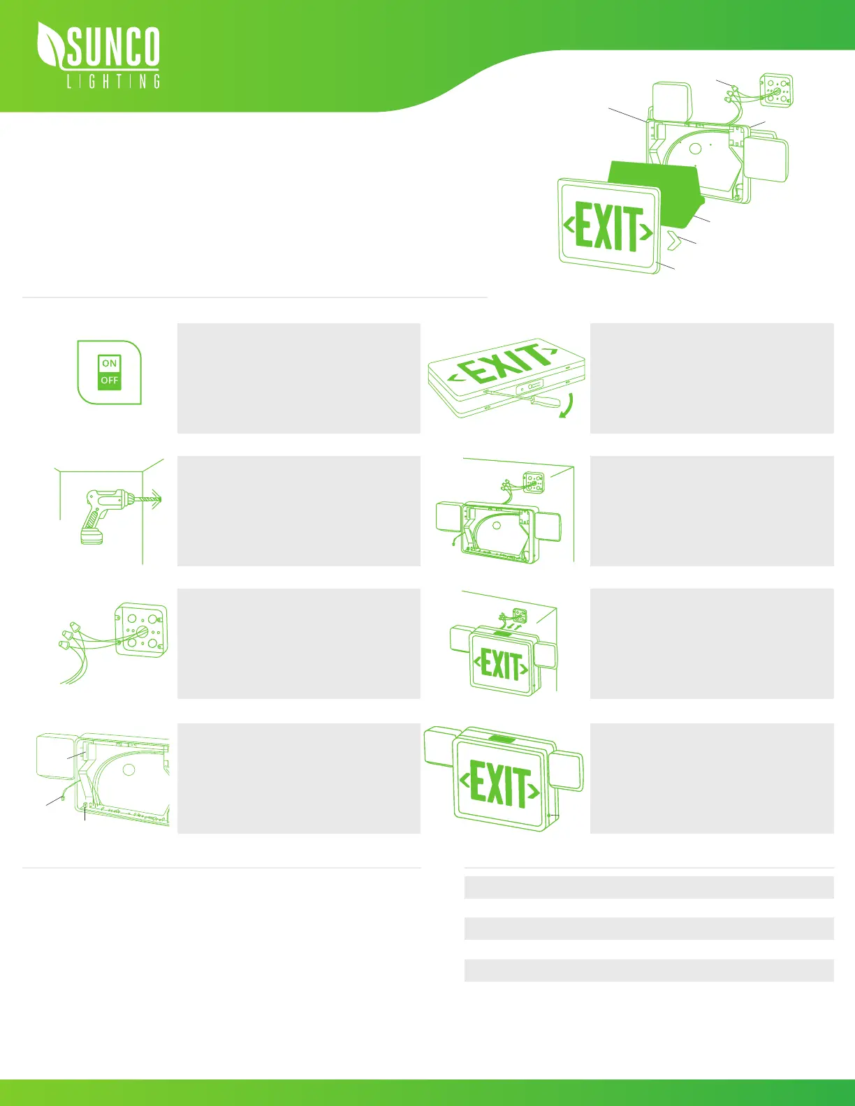
WALL MOUNT DIAGRAM
Charging time
The AC voltage
340.62 lm
6500 ± 500k
360°
90min
24h
120 - 277V
Color temperature
Swiveling flood lights
Backup battery
Luminous flux
When using electrical equipment, basic safety precautions should
always be followed. Consult local building codes for approved
wiring and installation.
• Do not use outdoors
• Do not mount near gas or electric heaters
• Cap unused wires with wire nuts
• Use caution when servicing batteries
• Equipment should be mounted securely in locations and at
heights where it will not be readily subjected to tampering by
unauthorized personnel.
WALL MOUNT
1.
3.
5.
7.
2.
4.
6.
8.
9.
10.
Disconnect AC power, make sure the battery is
unplugged before servicing
•If you are replacing an existing halogen fixture,
allowing the fixture to cool away from flammable
materials.
Drill holes for knockouts on the backplate that
correspond to junction box holes
Connect leads to AC input leads in the Junction Box.
Black wire for 120V, Red/Orange wire for 277V
•Cap off unused wires
•Feed excess wire into a junction box
Connect the battery (see figure)
•Snap housing on to the backplate
(first top then bottom)
Unsnap faceplate to open (see figure)
Feed lead wires through a hole in the center of
the backplate, ensure wires are secured into
wire guides
Fasten backplate to the junction box
•Snap housing to canopy
Snap-in arrows on EXIT faceplate as required
Secure faceplate to housing
Test after 24 hours of charging
Button
EXIT LED SIGN
Install Guide and Manual
Diffuser
Wire
Nuts
Snap-in
Directional Arrow
Exit Panel
Plastic
Housing
Back Plate
Turn Power OFF
Battery
Battery
Connector
Socket
 Loading...