Do you have a question about the Sunco EXIT LED SIGN and is the answer not in the manual?
Disconnect AC power and unplug the battery before servicing the fixture.
Unsnap the faceplate and canopy hole cover to access the interior.
Feed lead wires, connect to AC input, attach canopy, and connect the battery.
Secure faceplate, snap-in arrows, and test after 24 hours of charging.
Visual representation of components for ceiling mount installation.
Battery charging, testing procedures, and required tools for installation.
Disconnect AC power and unplug the battery before servicing.
Unsnap faceplate to open the unit.
Drill holes on the backplate for junction box alignment.
Feed lead wires, connect to AC input, and fasten backplate.
Connect battery, snap arrows, secure faceplate, and test.
Visual guide to wall mount installation components.
Essential safety precautions for electrical equipment installation.
Technical details including charging time, voltage, and luminous flux.
| Battery Backup | Yes |
|---|---|
| Light Source | LED |
| Certification | UL Listed |
| Power Source | AC |
| Housing Material | Plastic |
| Mounting Type | Wall, Ceiling |
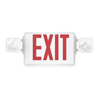
| Color | Red or Green |
| Battery | Ni-Cad |