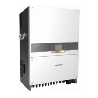
The SG80KTL-20 is a solar inverter designed for converting direct current (DC) electricity from solar panels into alternating current (AC) electricity for use in a grid-connected system. This quick installation guide provides essential information for setting up and commissioning the device, emphasizing safety and proper installation procedures.
Function Description:
The primary function of the SG80KTL-20 is to facilitate the conversion of solar energy into usable electrical power. It acts as the central component in a photovoltaic (PV) system, enabling the flow of electricity from PV strings to the electrical grid. The inverter is equipped with multiple Maximum Power Point Tracking (MPPT) inputs, allowing it to optimize power harvesting from different PV string configurations, even under varying sunlight conditions. It includes various electrical connections for both DC input from PV modules and AC output to the grid, along with communication ports for monitoring and control. The device incorporates protective features to ensure safe and reliable operation within the electrical system.
Usage Features:
The SG80KTL-20 is designed for straightforward installation and operation, though it requires adherence to specific guidelines to ensure safety and optimal performance.
- Installation Site Selection: The inverter requires careful consideration of its installation location. It should be mounted on a non-flammable wall, away from flammable materials or gases. Specific height requirements must be met to ensure proper air circulation and accessibility. The installation angle is also crucial, with guidelines for forward tilt, backward tilt, and upside-down mounting to prevent operational issues. Adequate clearance around the inverter, particularly on the side with fans, is necessary for effective cooling and maintenance access.
- Mounting: The installation process involves securing a backplate to a metal frame, marking and drilling holes, and then attaching the inverter to the backplate. The backplate is fastened with specific torque settings to ensure stability. The inverter is then slid onto the backplate and secured with screws. Handles are provided to assist with moving the inverter during installation.
- Electrical Connection: This is a critical phase requiring strict safety precautions. All DC and AC cables must be de-energized before beginning electrical work to prevent high voltage hazards. The connection cabinet is accessed by removing its front cover, revealing terminals for DC input, AC output, and communication.
- AC Connection: The guide details the selection of appropriate AC cable cross-sections and external diameters, with recommendations for different cable glands based on cable size. Specific torque values are provided for tightening AC cables to their terminals, varying by cable type (copper stranded, aluminum solid, aluminum stranded) and cross-section. The guide also specifies how to prepare sectorial AC cables for connection. It emphasizes the importance of correct terminal layout to avoid connecting phase cables to the PE terminal and advises against squeezing or pressing the cable insulation layer. Cables inside the lower part of the device should be bent with surplus length to prevent dropping or loosening due to self-weight or land subsidence.
- DC Connection: The process involves stripping insulation from DC cables, crimping contacts, leading cables through glands, inserting contacts into insulators, and tightening cable glands. Users are instructed to check the polarity of PV strings and ensure the open-circuit voltage does not exceed the inverter's input limit. DC input strings are connected following a specific numerical sequence. Unused DC terminals must be sealed with waterproof plugs.
- Second PE Terminal: A second protective earth (PE) terminal is provided and must be grounded reliably. This connection is supplementary and does not replace the PE connection of the AC cables.
- Communication Connection: The inverter supports RS485 communication, with dedicated terminals and an interface on the configuration circuit board. A 120Ω terminating resistor can be connected via a dip switch. Pin definitions for RJ45 connections are provided, specifying which pins correspond to RS485- B and RS485+ A.
- Commissioning: After all installations and connections are verified, the commissioning process begins. This involves rotating the DC switch to "ON," connecting AC and DC switches to the grid and PV string respectively. The LCD display activates when DC voltage exceeds the startup threshold. The guide provides instructions for navigating the LCD menu using specific buttons (ESC, ENTER, arrow keys) to select country codes, grid codes (e.g., GR_L, GR_IS, LV, MV, AG, YG), set the inverter time, and configure Modbus parameters. A "setting confirmation" screen allows users to review and confirm all parameters before startup.
- Startup Process: Upon successful commissioning, the inverter enters its startup process, indicated by the "RUN" LED and "Run" status on the LCD. If commissioning fails, a "FAULT" indicator will illuminate, and "Fault" will appear on the display, prompting users to view fault information and repeat procedures after resolving the issue.
Maintenance Features:
The SG80KTL-20 incorporates features and guidelines that contribute to its long-term reliability and ease of maintenance.
- Sealing Gaps: After electrical connections are made, all gaps between cables and glands inside the lower part of the cabinet must be sealed with fireproofing mud or other suitable materials. This prevents the entry of foreign bodies or moisture, which could compromise the inverter's internal components and ensure long-term normal operation.
- Internal Layout Access: The front cover of the connection cabinet can be removed by loosening six screws, providing access to the internal layout for inspection, wiring, and potential troubleshooting.
- Error Indication: The inverter's LCD display and LED indicators provide clear feedback on its operational status. In case of a fault, the "FAULT" indicator and "Fault" message on the display guide users to identify and address issues, facilitating prompt maintenance.
- Documentation: The device comes with a quality certificate, packing list, test report, CD, and a quick user manual, which are essential resources for installation, troubleshooting, and maintenance. The quick installation guide explicitly states that it does not substitute for the user manual, implying that more detailed maintenance information is available in the comprehensive manual.
- Supplier Contact: In case of missing contents or detected damage upon unpacking, users are instructed to contact their supplier, ensuring that any initial defects are addressed before installation.
- Cable Gland Replacement: The AC cable gland on the bottom of the device can be replaced if the external diameter of the selected AC cable does not match the original, allowing for flexibility in cable selection and proper sealing.
- Modular Connectors: The use of MC4 terminals for PV connection and waterproof connection terminals for communication simplifies wiring and potential replacement of components.