15
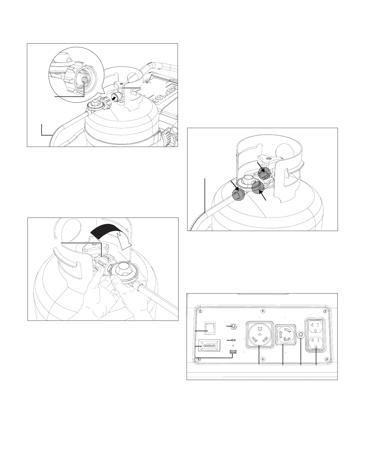
4. Holding the coupler and hose as shown, turn the coupler
clockwise and tighten by hand, taking care not to cross-
thread the connection. Do not use tools (Fig. 17).
NOTE: The hose will seal in the cylinder valve resulting in
some resistance. An additional one-half to three quarters
turn is required to complete the connection. If you
cannot complete the connection, disconnect and repeat
the above two steps. If you still cannot complete the
connection,DONOTusethispropaneconnectionhose!
5. Inspect valve connections port and propane connection
hose. Look for any damage or debris. Remove any debris.
Inspect hose for damage. Never attempt to use damaged
or plugged equipment. See your local propane dealer for
repairs.
LeakageTest
All connections of this generator have been checked at the
factory for leakage. However, in transportation and handling
some connections may have loosened. It's recommended to
run the leakage test every time before using.
mWARNING!
• Donotuseanopenametocheckforleakage.
• Donotsmokeduringtesting.
• Donottestindoors.
• Aleakcheckmustbeperformedwheneverthecylinderis
replaced.
NOTE: Use only the propane connecting hose supplied
withthisgenerator.Replaceitwiththosespeciedbythe
manufacturer only.
1. Make leakage solution by mixing 1 part liquid dish soap
and 3 parts water.
2. With the cylinder connected to the hose, spoon or brush
several drops (or use squirt bottle) of the solution onto the
connections along the hose, regulator and cylinder
(Fig. 18).
3. Turn on the cylinder. Inspect the connections and look for
bubbles. If no bubbles appear, the connection is safe. If
bubbles appear, there is leakage. Loosen and re-tighten
thisconnection.Ifthereisstillaleak,turnothecylinder
and contact the Snow Joe
®
+ Sun Joe
®
customer service
centerat1-866-SNOWJOE(1-866-766-9563).
ControlPanel(Fig.19)
A.Engineswitch–Use the engine switch to start the
generator.
B.Digitaldisplay–The display shows the amount of
time the generator has run since being started. It will
automatically reset when reached the Max. number it can
show.
Fig.16
Cylinder
valve
Cylinder
connecting
hose
Nipple
Fig.17
Coupler
Fig.18
Cylinder
connecting
hose
Fig.19
A
B
C
D
E
F
G
H I
 Loading...