5
Technical Data
Power Input .................................... 120 V AC | 60 Hz
Maximum Wattage ......................... 1500 W
Heat Output .................................... 5118 BTUs
Heating Area ................................... 130 sq. ft. (12 m
2
)
Power Cord Length ........................ 6.6 ft. (2 m)
Adjustable Height ........................... 5.25 ft. – 6 ft.
(1.6 m – 1.8 m)
Adjustable Heating Head Angle ..... 0º – 25º
Net Weight ...................................... 26.4 lbs (12 kg)
Unpacking
Carton Contents
• Heater head
• Telescoping pole
• Upper pole with telescoping coupler
• Middle pole
• Lower pole
• Base cover
• Base
• Metal safety bar
• Hardware pack (hex key wrench, base washer, heater head
knob, 4 wall anchors, 4 ST4x30 screws, M6x12 screw, wall-
mounting bracket)
• Heater head cover
• Manual with registration card
1. Carefully remove the infrared heater and check to see that
all of the above items are supplied.
2. Inspect the product carefully to make sure no breakage or
damage occurred during shipping. If you nd damaged or
missing parts, DO NOT return the unit to the store. Please
call the Snow Joe
®
+ Sun Joe
®
customer service center at
1-866-SNOWJOE (1-866-766-9563).
NOTE: Do not discard the shipping carton and packaging
material until you are ready to use your new infrared
heater. The packaging is made of recyclable materials.
Properly dispose of these materials in accordance with
local regulations.
IMPORTANT! The equipment and packaging material are not
toys. Do not let children play with plastic bags, foils or small
parts. These items can be swallowed and pose a suocation
risk!
Assembly
Tools Required:
• Phillips screwdriver (not provided)
• Hex key wrench
• Drill (not provided)
Choose a spacious and level location for assembly. Remove all
parts from the packaging, and check for missing parts.
Floor Stand Set-up
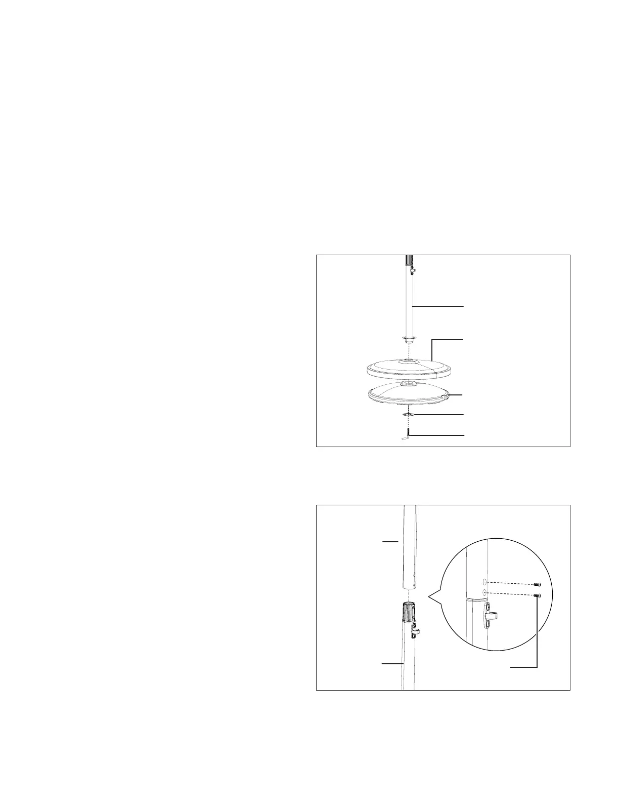
1. Put lower pole through the base cover, base, and base
washer, tightly lock them with the provided hex key
wrench (Fig. 1).
2. Unscrew the 2 pre-assemble M6x12 screws from the
middle pole, connect the middle pole with the lower pole,
aligning the holes, and tighten with the 2 M6x12 screws
(Fig. 2).
3. Loose the pre-assembled telescoping coupler on the
upper pole, then insert the telescoping pole through the
bottom of upper pole (Fig. 3).
Fig. 1
Lower pole
Base cover
Base
Base washer
Hex key wrench
Fig. 2
Middle pole
Lower pole
M6x12 screw
 Loading...