SUNPOWER CORPORATION
Safety and Installation Instructions - Document 001-15497 Rev U
©September 2020 SunPower Corporation. All rights reserved. Specifications included in this manual are subject to change without notice.
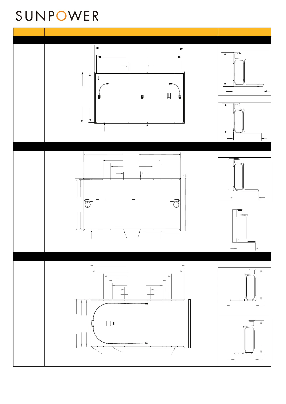
Platform Module mounting and ground hole detail Frame Profile
FOR P3 UPP GEN 4.3 ( Customized)
Commercial
Modules
SIDE FRAME PROFILE
END FRAME PROFILE
FOR P5 UPP GEN 4.3
SIDE FRAME PROFILE
END FRAME PROFILE
FOR MAX5 GEN 4.2 MODULES
Commercial
Modules
SIDE FRAME PROFILE
END FRAME PROFILE
2066 mm
MODEL: SPR-P19-410-COM
Rated Power (Pmax)
1
(+5/
0
%) 410
W
Voltage (Vmp) 43.9
Current (Imp) 9.35
Open-Circuit Voltage (Voc)
53.1
Short-Circuit Current (Isc) 9.94
Maximum Series Fuse 15
1
Standard Test Conditions: 1000 W/m
2
, AM 1.5, 25° C
Suitable for ungrounded, positive, or negative grounded DC systems
Field Wiring: Cu wiring only, min. 12 AWG/4 mm
2
, insulated for 90° C min.
WARNING
SEVERE ELECTRICAL HAZARD
• Solar module has full voltage even in very low light.
• Installation should only be done by a qualified technician.
527040
www.sunpower.com
Patented as shown at www.sunpower.com/patents
Safety Class II
Fire Rating: Class C
Max. System Voltage:1500 V DC
274 mm
1160 mm
4X Ø4.2 mm
Ground Holes
8X 14mm(L) x 9mm(W)
R4.5mm
Mounting Holes
1118 mm
2022 mm
35 mm
35 mm
35 mm
35 mm
1092 mm
1043 mm
400 mm
1100 mm
1400 mm
2362 mm
4X Ø4,2mm
Ground Holes
8X 14mm (L) x 9mm (W)
R4,5mm
SLOTS
8X 10mm (L) x 7mm (W)
R3,5mm
Mounting Holes
35 mm
35mm
35 mm
16 mm
35 mm
1935 mm
1423 mm
1200 mm
539 mm
400 mm
973 mm
980 mm
1058 mm
1999 mm
1016 mm
20x Ø6.8
Mounting Holes
4x Ø4.22
Ground Holes
4x 5mm(W) x 15mm (L)
SLOTS
32 mm
40 mm
24 mm
40 mm
Measurement Tolerances are +/-3 mm for the Length and Width of the Module.
 Loading...