6
3 b) Installation: one system on rack or roof. (Horizontal only)
1 - Mounting kit (part # SQ-RMK5) is required
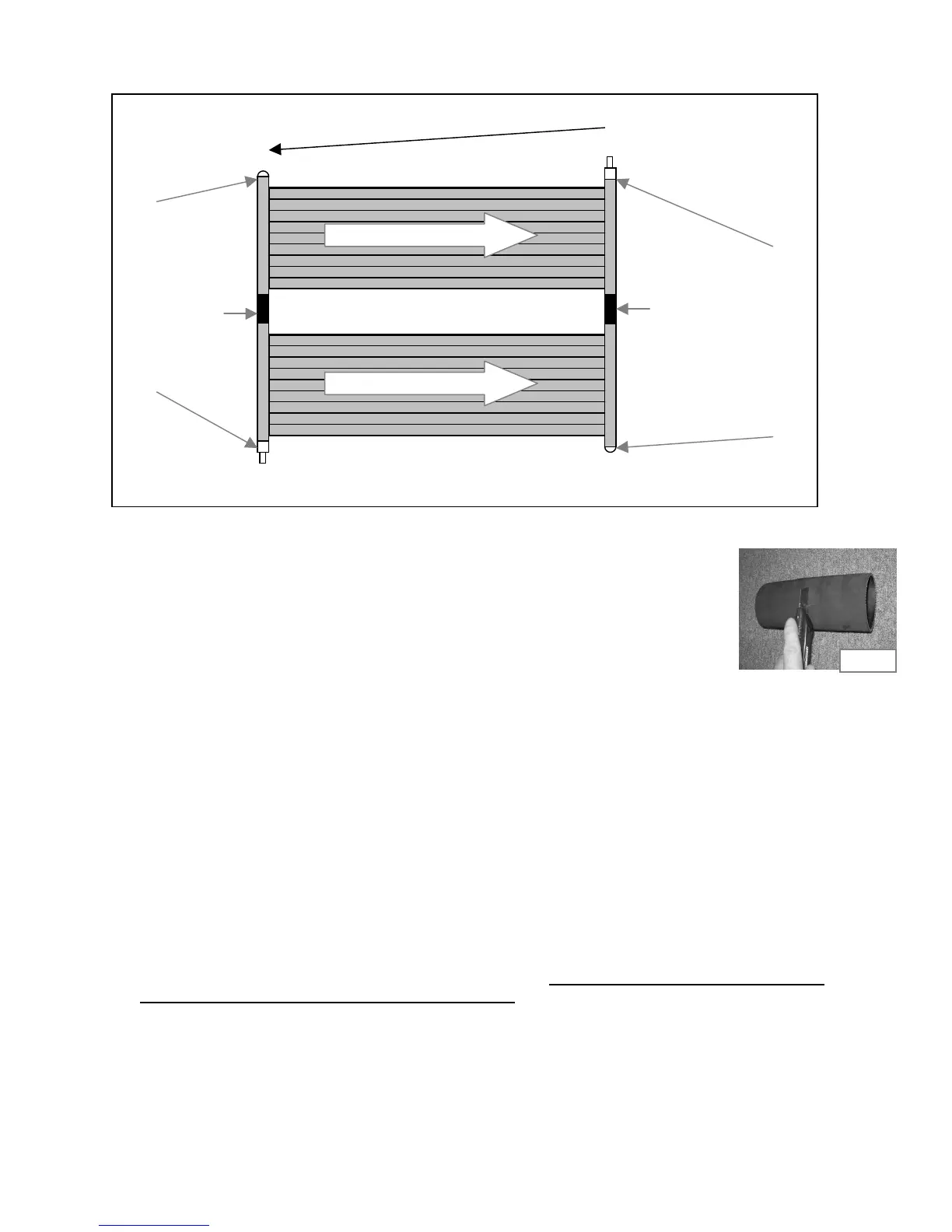
Diagram Step 3b
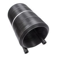
• Using a utility knife or a hand saw, cut rubber hose (SK-FTG-J) in half. Make sure
you cut it as straight as possible. See Fig 3b-1. You should now have two rubbers
3 ¾" long.
• Apply Teflon on two of the caps (SK-FTG-F). See Fig 3a-1.You only need 2 of the 4
caps for this type of installation.
• Thread the 2 caps into the panels as per Diagram Step 3b. Do not over tighten.
See Fig 3a-2
• Put "O" rings (SK-FTG-I) on both combination adapters (SK-FTG-D). See Fig 3a-3
• Thread both combination adapters into the panels as per Diagram Step 3b.
Do not over tighten. See Fig 3a-4
• Push the rubber hose you cut in half previously over the panel header as per Diagram
Step 3b. Slide a metal collar (SK-FTG-L) onto the rubber hose. Place metal collar
1
/
4
"
from edge and tighten collar with screwdriver. See Fig 3a-5. Repeat for other end of panel.
• Slide another metal collar onto the rubber hose. Connect the 2 panels together by pushing
the rubber hose over the second panel header. Tighten metal collar to secure assembly.
See Fig 3a-6. Repeat for other end of panel.
• Install mounting kits as per instructions included with them. Panels must be installed with a slight
slope (minimum 1 inch per 10 feet) toward the inlet. This will allow the panel to drain properly.
Note: The inlet must always be at the lower end of the panel and the outlet at the higher end of the panel.
3.75"
3.75"
Fig 3b-1
Inlet
Outlet
A Minimum of 1 inch fall per 10 feet