9
3 d) (cont.)
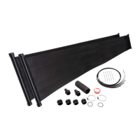
• Apply Teflon on reducer adapter (SK-FTG-M) included in the system kit (SQ-SK) sold
separately. Thread reducer adapter into the panel as per diagram Step 3d.
Do not over tighten. See Fig 3d-3.
• Apply Teflon on vacuum relief valve (SK-VRV). Thread vacuum relief valve into
the reducer adapter. Do not over tighten. See Fig 3d-3.
Note : The vacuum valve assembly must be installed at the top of the panels as per diagram Step 3d.
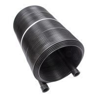
• Push the rubber hose you cut in half previously over the panel header as per diagram Step 3d. Slide a metal
collar (SK-FTG-L) onto the rubber hose. Place metal collar
1
/
4
" from edge and tighten collar with screwdriver.
See Fig 3a-5. Repeat for other end of panel.
• Slide another metal collar onto the rubber hose. Connect the 2 panels together by pushing the rubber hose
over the second panel header. Tighten metal collar to secure assembly. See Fig 3a-6. Repeat for other end of
panel.
• Repeat previous 2 steps for other system.
• You should now have two sets of connected panels. You need to use rubbers from the system
kit (SK-FTG-K) to connect the two set together as per Diagram Step3d.
• Install mounting kits as per instructions included with them. Panels must be installed with a slight
slope (minimum 1 inch per 10 feet) toward the inlet. This will allow the panel to drain properly.
Note: The inlet must always be at the lower end of the panel and the outlet at the higher end of the panel.
Note: A maximum of 12 2ft panels ( 6 systems ) may be plumbed in parallel
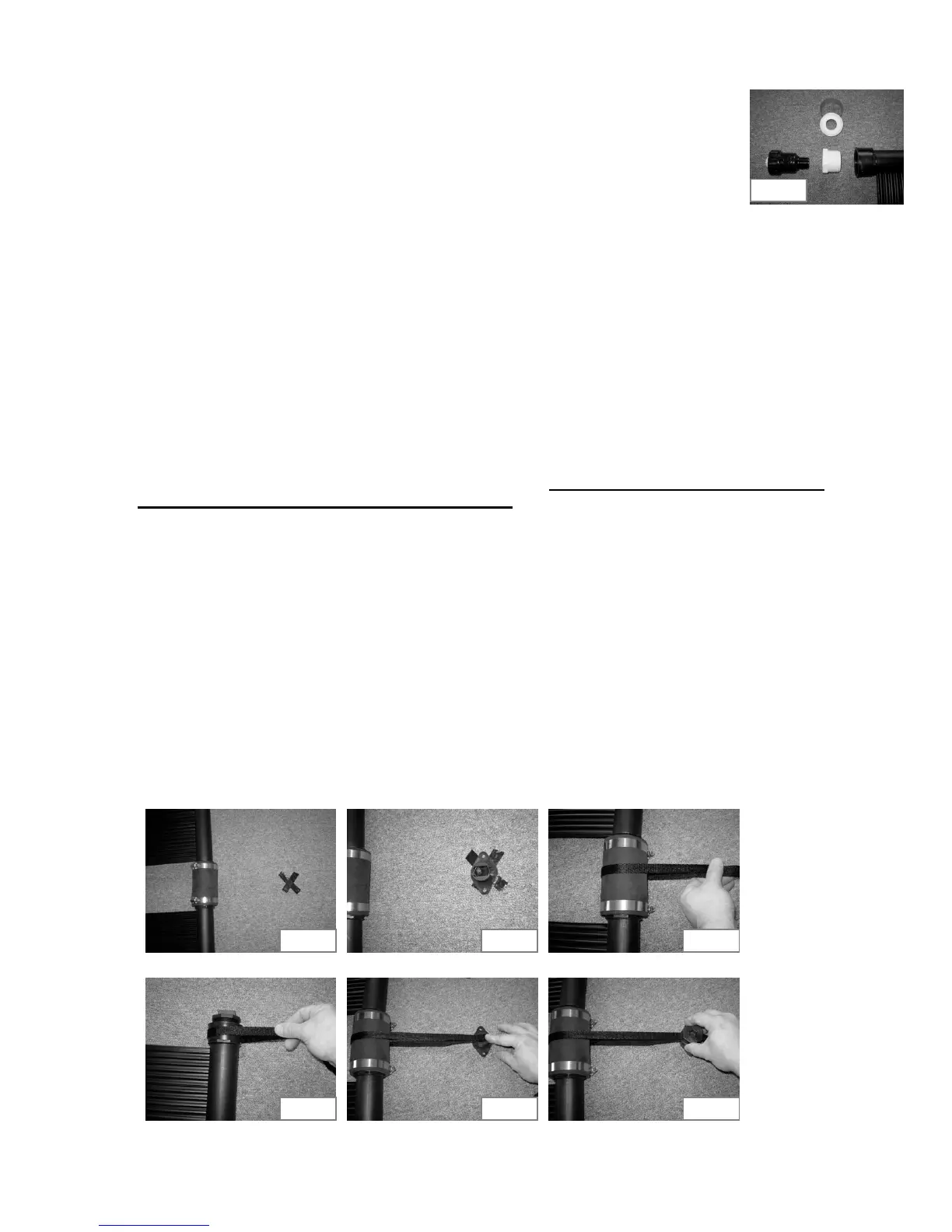
• For high wind areas you can install the Nylon straps and Vinyl straps from System Kit.
Mark a spot 6" to the right of the outlet. Mark spots 6" to the right of every second
rubber hose that are on the same side as the outlet. Mark a spot 6" to the right of the
cap. See Fig 3d-4. Place mounting base (SK-RMK-BASE) on these spots. Drill pilot
holes, apply silicone roof sealant and screw mounting base into roof. See Fig 3d-5.
Wrap a Nylon strap (SK-RMK-ST-N32) around the panel header (see Fig 3d-7) or
around rubber hose (see Fig 3d-6). Lay both ends of strap in the mounting base and
pull tight. See Fig 3d-8. Screw on mounting cap (SK-RMK-CAP). See Fig 3d-9.
Repeat process on the inlet side of the panels but using the Vinyl straps (SK-RMK-ST-V32)
instead.
Fig 3d-3
Fig 3d-6Fig 3d-5Fig 3d-4
Fig 3d-7 Fig 3d-8 Fig 3d-9
 Loading...