STEP 7. NOTE THE ORIENTATION OF THE EASYSHADE PANEL, hemmed (folded) edges on the top and bottom
facing toward the rear of the shade assembly.
STEP 8. With your helper, slide the old EasyShade panel out of the shade assembly.
STEP 9. Remove the new EasyShade panel from its package and orient it the same way as explained in Step 7.
STEP 10. With your helper, slide the new EasyShade panel into the slot in the roller bar inside the shade assembly.
Trim the small gray cord so that it is even with the ends of the roller bar.
STEP 11. Reinstall the nylon roller cap into the EasyShade roller bar and secure the end cap with two Phillips screws.
See Figure 2.
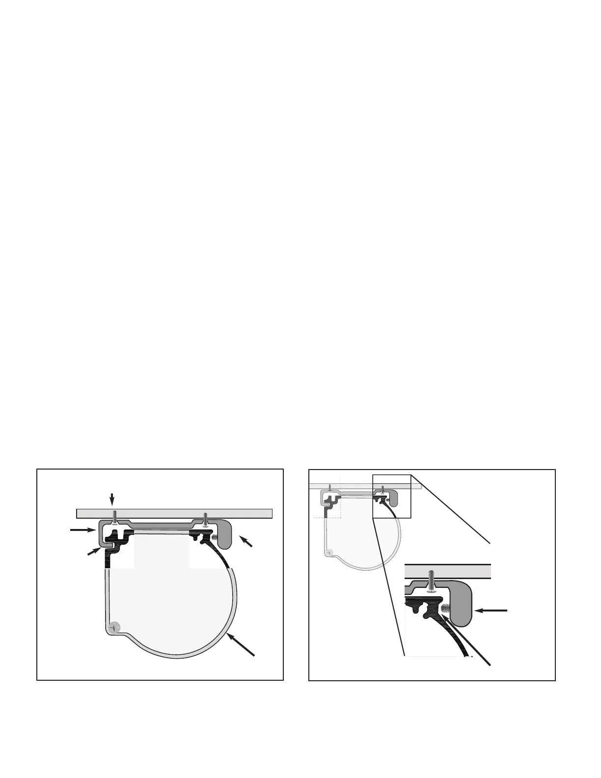
STEP 14. With your helper, lift the shade assembly up to the installed mounting brackets and insert the top groove of the
shade assembly onto the protruding tab on the mounting brackets. (See Figure 3). While maintaining upward pressure to
keep the top groove of the shade assembly on the tab of the mounting brackets, press the shade assembly, toward the
mounting bracket and be sure that the set screw is aligned in the recessed portion of the shade assembly. See Figure 3a.
Revised 5/4/07 SunSetter Products, a Massachusetts Limited Partnership, 184 Charles Street, Malden, MA 02148
STEP 6. Remove the nylon roller cap at the end of the EasyShade roller bar. See Figure 2.
STEP 12. Slide the PVC tube into the bottom sleeve of the new EasyShade panel.
STEP 13. Orient the shade assembly so that the crank loop is on your right as you face the installed brackets.
STEP 15. Tighten the set screw in each mounting bracket until the shade assembly is secure. See Figure 1.
©
STEP 16. Test the EasyShade panel for proper operation, by rolling up and unrolling the panel.
- - - - - - - - - - -
- - - - - - - - - - - - - - - - -
- - - - - - - - - - - - -
- - - - - - - - - - - - - - - - -
Set Screw
Shade Assembly
#8 x 1 Round
Head Screw
1
/2
Mounting
Bracket
Top Groove
Figure 3
- - - - - - - - - - - - - - - -
- - - - - - - - - - - - -
- - - - - - - - - - - - - - - - -
- - - - - - - - - - - - -
- - - - - - - - - - - - - - - - -
- - - - - - - - - - -
- - - - - - - - - - - - - - - - -
- - - - - - - - - - - - -
- - - - - - - - - - - - - - - - -
-
Figure 3a
Set Screw
Recessed Area
 Loading...