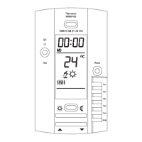
MODEL 500500-120 (120 VAC)
SUMMARY
TO CHANGE THE TEMPERATURE SCALE FROM °C (CELSIUS)
TO °F (FAHRENHEIT) AND BACK
Switch the dip switch on the back of the control to either °C or °F.
Note: The other three dip switches are not used.
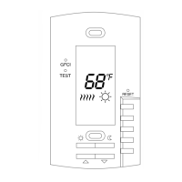
TO SET TEMPERATURE
Press on or once to see setpoint temperature appear on
display. Every subsequent press will change the setpoint tempera-
ture by one degree.
TO RECORD THE (COMFORT) SETPOINT TEMPERATURE
Select chosen setpoint temperature by using or button. Press
on button (2 to 3 seconds) until icon appears on display.
TO RECORD THE (ECONOMIC) SETPOINT TEMPERATURE
Select chosen setpoint temperature by using or button. Press
on button (2 to 3 seconds) until icon appears on display.
CHECKING GROUND FAULT CIRCUIT INTERRUPTER (GFCI)
Adjust the setpoint temperature until heating indicator (flames)
appears on display. Press TEST button. The test is conclusive if the
warning light (GFCI) on thermostat is ON and power to the load is
cut-off (flames remain on display though). If these events do not
occur, check the installation. Press on RESET button to reset the
GFCI.
INSTALLATION
Parts included:
One (1) 500500-120 (120 VAC) thermostat
Two (2) 6-32 screws
Four (4) Solderless connectors (for copper wire)
One (1) Temperature sensor with a 15-foot extension
TURN OFF POWER TO THE HEATING SYSTEM AT THE MAIN
POWER PANEL TO AVOID ELECTRICAL SHOCK. KEEP AIR VENTS
OF THE THERMOSTAT CLEAN AND FREE OF OBSTRUCTIONS.
This thermostat should be installed by an electrician or experienced
technician. The thermostat must be used with a self-protected
heating system equipped with a thermal cut-off and circuit breaker or
fuse.
This thermostat was designed to control floor electric heating
systems. The resistive load must not exceed 1920 watts at
120 VAC (16.0 A). The thermostat is equipped with a ground
fault circuit interrupter (GFCI) and therefore the isolation of the line
and load is required for operation. The polarity of line connection
must be respected. During a ground fault, only the current in
the black wire of the load will be cut-off. Connect thermostat as
shown on diagram.
1. CONNECTING WIRES AND MOUNTING THERMOSTAT
Connect the rear thermostat wires to the power supply and to the
load using solderless connectors for copper wires. See schematic
diagram below.
Push the excess wire back into the electrical box to prevent interfer-
ence withthe thermostat. Secure the thermostat using two (2)
6-32 screws 1-1/4 inches long. Once the thermostat is properly
installed, return power to heating system.
2. CONNECTING TEMPERATURE SENSOR WIRE
Connect the sensor wire to the two lower screws of the terminal
block at the back of the thermostat (no polarity need to be
respected). The wire must pass outside the electrical box and follow
the wall down to the floor. The sensing probe should be placed in a
representative heat area for maximum system perfomance. The
sensing probe should be centered between the wires in the mat.
The probe wire cannot cross any heater wires and the temperature
sensor must not be directly or adjacent to a heating wire.