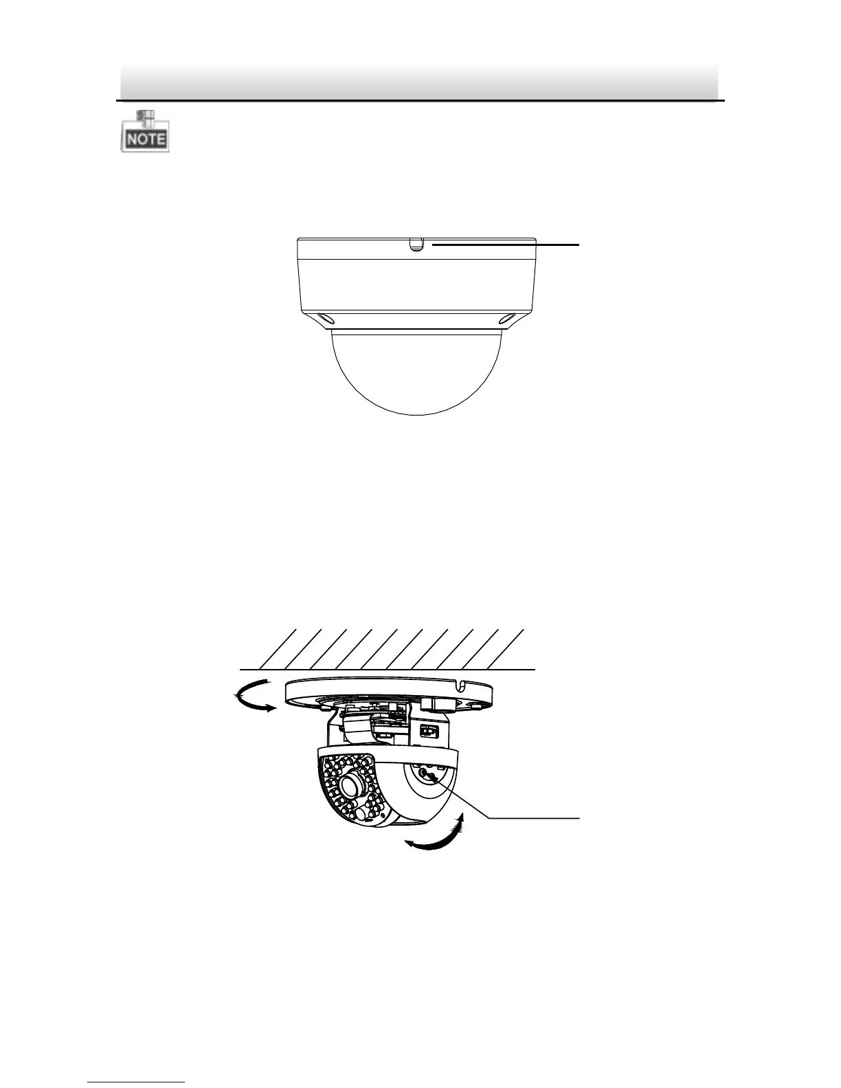
If required, you can route cables through the side opening on the
side of the mounting base.
Side Opening Figure 2-4
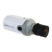
4. Loosen the tilt lock screws, adjust the tilting position in a range
of 65 degrees, and tighten the tilt lock screws.
5. For type I camera--Rotate the black liner to adjust the pan angle
[0°~360°] and tilt angle [0°~65°].
Type I Camera Angle Adjustment Figure 2-5