Test Equipment Required
1) CPU and Phase Locked Loop Section
1 Frequency Counter
2 DC Power Supply
3 DC Volt Meter
4 Oscilloscope
2) Transmitter Section
1 RF Power Meter (RF SSVM)
2 50Ω Load (non-inductive)
3 RF Attenuator
4 Oscilloscope
5 Audio Generator
6 DC Power Supply
7 Spectrum Analyzer
8 Frequency Counter
9 Coupler
3) Receiver Section
1 RF Signal Generator
2 RF Power Meter
3 Distortion Meter
4 DC Power Supply
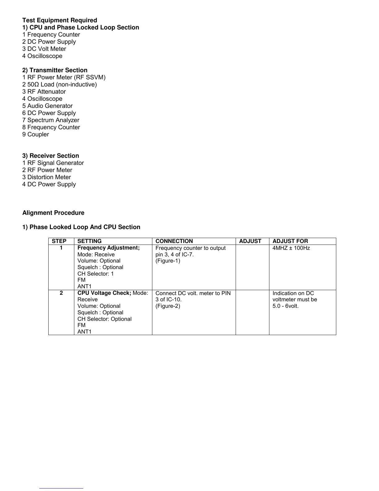
Alignment Procedure
1) Phase Looked Loop And CPU Section
STEP SETTING CONNECTION ADJUST ADJUST FOR
1 Frequency Adjustment;
Mode: Receive
Volume: Optional
Squelch : Optional
CH Selector: 1
FM
ANT1
Frequency counter to output
pin 3, 4 of IC-7.
(Figure-1)
4MHZ ± 100Hz
2 CPU Voltage Check;
Mode:
Receive
Volume: Optional
Squelch : Optional
CH Selector: Optional
FM
ANT1
Connect DC volt. meter to PIN
3 of IC-10.
(Figure-2)
Indication on DC
voltmeter must be
5.0 - 6volt.
 Loading...