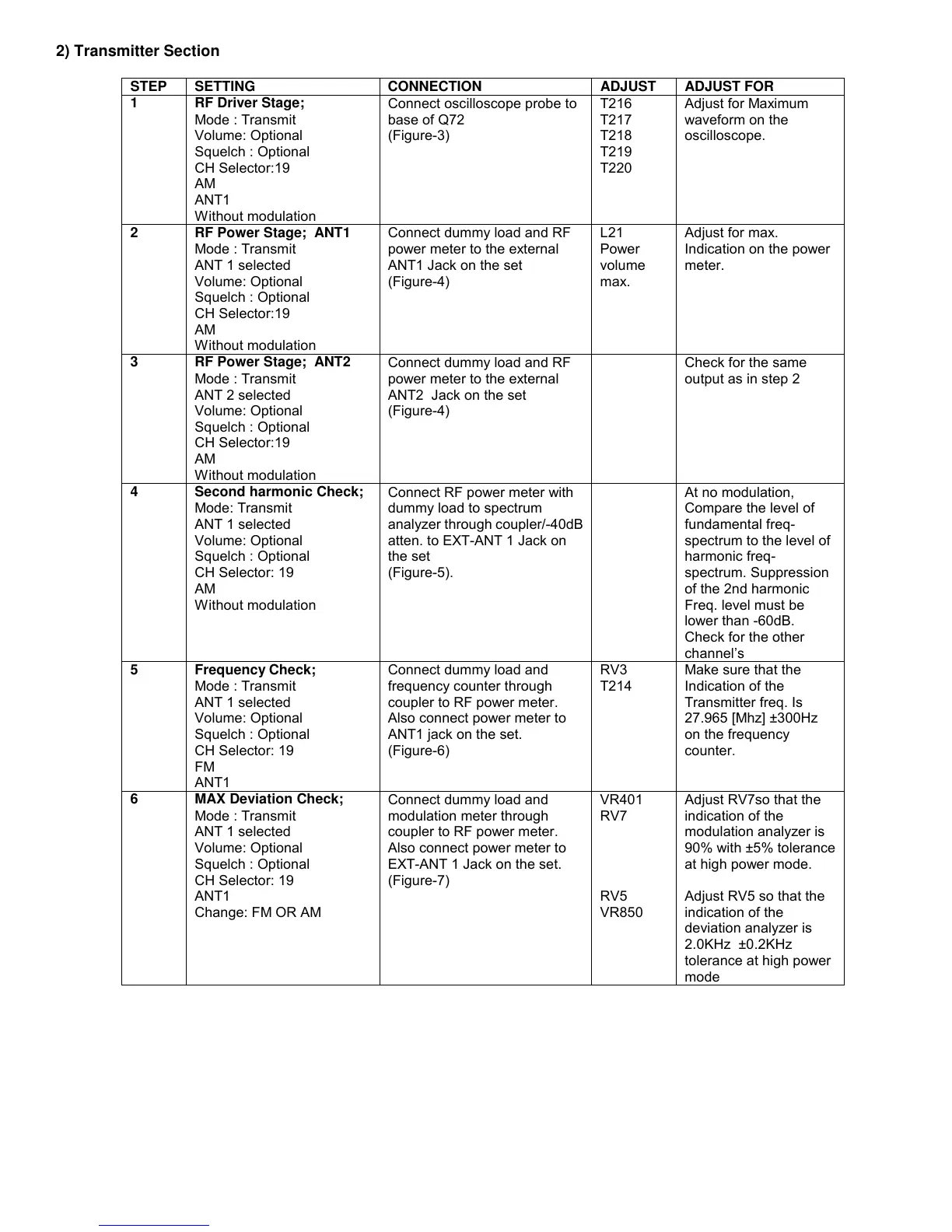
2) Transmitter Section
STEP SETTING CONNECTION ADJUST ADJUST FOR
1 RF Driver Stage;
Mode : Transmit
Volume: Optional
Squelch : Optional
CH Selector:19
AM
ANT1
Without modulation
Connect oscilloscope probe to
base of Q72
(Figure-3)
T216
T217
T218
T219
T220
Adjust for Maximum
waveform on the
oscilloscope.
2 RF Power Stage; ANT1
Mode : Transmit
ANT 1 selected
Volume: Optional
Squelch : Optional
CH Selector:19
AM
Without modulation
Connect dummy load and RF
power meter to the external
ANT1 Jack on the set
(Figure-4)
L21
Power
volume
max.
Adjust for max.
Indication on the power
meter.
3 RF Power Stage; ANT2
Mode : Transmit
ANT 2 selected
Volume: Optional
Squelch : Optional
CH Selector:19
AM
Without modulation
Connect dummy load and RF
power meter to the external
ANT2 Jack on the set
(Figure-4)
Check for the same
output as in step 2
4 Second harmonic Check;
Mode: Transmit
ANT 1 selected
Volume: Optional
Squelch : Optional
CH Selector: 19
AM
Without modulation
Connect RF power meter with
dummy load to spectrum
analyzer through coupler/-40dB
atten. to EXT-ANT 1 Jack on
the set
(Figure-5).
At no modulation,
Compare the level of
fundamental freq-
spectrum to the level of
harmonic freq-
spectrum. Suppression
of the 2nd harmonic
Freq. level must be
lower than -60dB.
Check for the other
channel’s
5 Frequency Check;
Mode : Transmit
ANT 1 selected
Volume: Optional
Squelch : Optional
CH Selector: 19
FM
ANT1
Connect dummy load and
frequency counter through
coupler to RF power meter.
Also connect power meter to
ANT1 jack on the set.
(Figure-6)
RV3
T214
Make sure that the
Indication of the
Transmitter freq. Is
27.965 [Mhz] ±300Hz
on the frequency
counter.
6 MAX Deviation Check;
Mode : Transmit
ANT 1 selected
Volume: Optional
Squelch : Optional
CH Selector: 19
ANT1
Change: FM OR AM
Connect dummy load and
modulation meter through
coupler to RF power meter.
Also connect power meter to
EXT-ANT 1 Jack on the set.
(Figure-7)
VR401
RV7
RV5
VR850
Adjust RV7so that the
indication of the
modulation analyzer is
90% with ±5% tolerance
at high power mode.
Adjust RV5 so that the
indication of the
deviation analyzer is
2.0KHz ±0.2KHz
tolerance at high power
mode
 Loading...