6
Installation
Fig. B Determine the location of the lter. Provide a dry sheltered place (not in direct sunlight) and a stable at surface
with sucient space around for maintenance.
• NOTICE! A gravity lter must be installed at pond level or above. Recommendation is to build a base for the gravity
lter system to sit upon, using the correct materials, connectors, pipes etc Ask for advice from your pond specialist
or engage an installation company.
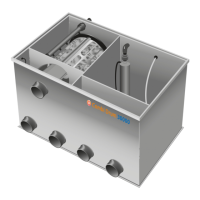
• The height of the minimum/maximum water level of the lter is marked on the partition panel of the lter (i).
Place the lter at such a height that the maximum water level in the pond never exceeds the maximum water
level in the lter.
• Place a pump suitable for dry installation (max. pump capacity 17,500 L/h) “behind” the lter.
• Connect the pump to one of the lter outlets (b) (ø 110 mm) using a exible socket. Close the other inlet with the
cap provided.
• NOTICE! The pipe connections (ø 110 mm) on the lter can NOT be glued, use exible rubber sockets.
• Connect both inlets (a) (ø 110 mm) to the pipes to the bottom drains and skimmer in the pond using exible
sockets.
• Connect the drain channel (c) (ø 110 mm) to a drain (e.g. sewer) using a exible socket.
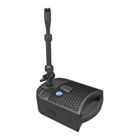
Fig. C Unscrew the plastic coupling from the bottom of the intake pipe (l) of the spray system.
• Remove the rinse pump (k) from its packaging and screw the plastic connector into the top of the rinse pump by
hand.
• Place the hole under the intake pipe (l) of the spray system and tighten the lock nut rmly.
• Place the capacitor box of the rinse pump in a safe and dry place near the lter.
• NOTICE! The rinse pump on/o switch is located on the side of the capacitor box, make sure it is switched on when
you put the system into operation.
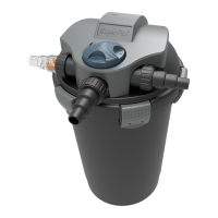
Fig. D Connect an air pump (min. 1200 L/h, not supplied) to the quick-connection (q) of the lter using a ø 12 mm
reinforced air tube (not supplied).
• Remove the protective cap from the air stone inlet (e) and connect the transparent air tube (p).
• Install the immersion UVC (u) (check the separate user manual of the UVC for correct installation).
• Check that the oater is pushed all the way down, this is the factory default setting. The oater is easily adjusted
in height by pulling it up or pushing it down.
• Fill the pond with water, the water runs through the bottom drains to the lter. Due to the law of communicating
vessels, the water level in the lter will be as high as in the pond. Stop lling as soon as the maximum water level
(i) in the lter is reached.
• In the meantime, check all connections, pipes, etc. for any leaks.
Fig. E Place the control box (h) in a safe and dry place near the lter.
• Connect the cable (f) of the oater (s) with the cable (g) of the control box. This DMX connection is watertight and
therefore sometimes dicult to t (if required, squeeze the outside of the mating plug (f) while inserting the
other plug). Tighten the union nut hand-tight.
• Insert the plugs of the rinse pump (k), immersion UVC (u), electro motor (m) and pond pump (d) into the
appropriate sockets on the control box. See markings on the control box. Provide the cables with drip loops so
that no water can run along the cables into the control box.
• Plug the control box into the socket, making sure there is a drip loop here as well.