NOTE:DIAGRAMS&ILLUSTRATIONARENOTTOSCALE.
8
Consult all local codes.
Properly size and route the gas supply line
from the supply regulator to the area where the
applianceistobeinstalled perrequirements
outlined in the National Fuel Gas Code, NFPA
54-latestedition(USA)orB149-latestedition
(Canada).Neverusegalvanizedorplasticpipe.
Gas lines must be routed, constructed and made
of materials that are in strict accordance with
localcodesandregulations.Werecommend
thataqualiedindividualsuchasaplumber
orgastterbehiredtocorrectlysizeandroute
the gas supply line to the appliance. Installing
a gas supply line from the fuel supply to the
appliance involves numerous considerations of
materials,protection,sizing,locations,controls,
pressure, sediment, and more. Certainly no one
unfamiliarandunqualiedshouldattemptsizing
or installing gas piping.
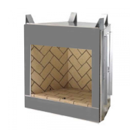
Remove the gas line access cover plate on either
theleftorrightsideofthereplace(seeFigure
8 showing locations).
Install1/2"min.to1-1/2"max.insidediameter
approvedgaslinethroughthereboxwallfor
connection to the Vent-Free room heater inside
the rebox. Connect the gas line before the
reboxisenclosedinthenishedwall.Gasline
holes and other openings should be caulked with
high temperature caulk or stuffed with unfaced
berglassinsulation.
Ensure that a sediment trap is installed in the
existinggasline,ifnot,installasedimenttrap
upstream of the heater to prevent moisture
and contaminants from passing through trap
to the heater controls and burners. Failure to
do so could prevent the heater from operating
reliably.
Anexternalregulatormustbeusedonallpro-
pane(L.P.G).heaters,inadditiontotheregulator
ttedtotheheater,toreducethesupplytank
pressureto13"W.C.(maximum).Anycopper
tubingusedtosupplypropane(L.P.G).from
the tank must be internally tinned.
INSTALLATION
Gas Line Installation
ASSEMBLY STEPS
Notes:
• Illustrations shown in this manual reect
“typical” installations with nominal dimen-
sions and are for design and framing refer-
ence only. Actual installations may vary due
toindividualdesignpreferences.However,
always maintain minimum clearances to
combustible materials and do not violate any
specicinstallationrequirements.Referto
theFramingSpecicationsFigure
s
on Page
11.
• Thefollowingstepsrepresentthenormal
sequenceofinstallation.Eachinstallation
is unique, however, and might require a
differentsequence.
Step 1.Position reboxprior toframing or
into prepared framing.
Step 2. Field wire the main power supply to
the appliance if a blower kit is to be installed
(at the time of installation or a later date).
Anoptionaljunctionboxkitandblowerkitisre-
quired(seePage 15
for ordering information).
Follow the installation and wiring instructions on
Pages 12 through 14). Electrical connections
shouldonlybeperformedbyanexperienced,
licensed/certiedtradesman.
Step 3. Plumb gas line. (Gas connections
shouldonlybeperformedbyanexperienced,
licensed/certiedtradesman).
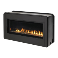
Step 4. Install decorative type Vent-Free room
heater per the instructions provided with the
Vent-Free room heater.
Step 5. Complete nish wall material, sur-
roundandoptionalhearthextensiontoyour
individual taste.
TESTALLCONNECTIONSFORGASLEAKS
(FACTORY AND FIELD)
Test allgasjoints fromthe gasmeterto the
gas heater regulator for leaks using a gas leak
test solution (also referred to as bubble leak
solution).
Note: Using a soapy water solution as a leak
detection solution is not recommended because
thesoapresiduethatisleftonthepipes/ttings
can result in a false-positive leak detection reading
if a gas leak sniffer is used. Soap residue can also
result in corrosion over time.
DO NOT USE AN OPEN FLAME TO CHECK
FORLEAKS.
Leak Test Procedure:
Turn on gas supply and test for gas leaks using
a gas leak test solution.
A.Light the appliance (refer to the lighting
instructions label provided with gas logs).
B. Brushalljointsandconnectionswiththegas
leak detection solution. If bubbles are formed,
or gas odor is detected, turn the gas control
knob(off/pilot/on)tothe“OFF”position.Either
tighten or refasten the leaking connection, then
retest as described above.
C.Whenthegaslinesaretestedandfoundto
be leak free, rinse off the leak testing solution
fromgaslinettings.
WARNING
Connecting directly to an unregu-
lated propane (L.P.G.) tank can
cause an explosion.
CAUTION
Plumbing connections should
only be performed by a qualified,
licensed plumber. Main gas supply
must be off when plumbing gas
line to fireplace or performing
service.
IMPORTANT
Hold heater regulator with a wrench
to prevent movement when connect-
ing to inlet piping.
WARNING
Check Gas Type: The gas supply
must be the same as stated on the
heater’s rating plate. If the gas
supply is different, DO NOT INSTALL
the heater. Contact your dealer for
the correct model.
IMPORTANT
Pack unfaced fiberglass insulation
material (not provided) around the
gas line access hole on appliance
and all exterior gas line penetra-
tion holes.